
User Manual


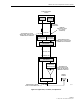
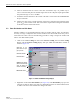


Table Of Contents
- SECTION 1: Overview
- SECTION 2: Description
- SECTION 3: Host Unit Installation
- SECTION 4: Operation
- SECTION 5: Maintenance
- SECTION 6: General Information
- ABOUT THIS MANUAL
- RELATED PUBLICATIONS
- ADMONISHMENTS
- GENERAL SAFETY PRECAUTIONS
- STANDARDS CERTIFICATION
- LIST OF ACRONYMS AND ABBREVIATIONS
- SECTION 1: Overview
- SECTION 2: Description

ADCP-75-116 • Issue A • August 2001 • Section 4: Operation
Page 4-6
©
2001,
ADC
Telecommunications,
Inc.
2.2 Determine Baseline Forward Path Input Signal Level
The
level
of
the
composite
RF
output
signal
at
the
FORWARD
RF
IN
port
at
the
HU
will
vary
depending
on
the
type
of
BTS,
the
cable
loss,
and
the
number
of
channels
present.
To
interface
with
the
HU,
the
baseline
signal
level
of
the
composite
forward
path
RF
signal
must
be
adjusted
to
fall
within
a
range
of
–25
to
–35
dBm.
If
the
signal
level
is
not
within
this
range,
it
must
be
adjusted
to
this
level
through
the
use
of
an
external
attenuator.
Use
the
following
procedure
to
measure
and
adjust
the
input
RF
signal
level
at
the
HU:
1. Connect
a
spectrum
analyzer
or
power
meter
to
the
forward
path
output
port
at
the
BTS.
The
required
signal
levels
and
test
points
are
shown
in
Figure 4-3.
2. Measure
the
RF
level
of
a
single
carrier,
such
as
the
control
channel,
in
dBm.
Make
sure
the
resolution
bandwidth
of
the
spectrum
analyzer
or
power
meter
is
narrow
enough
to
measure
the
power
of
the
single
30
kHz
channel
only.
3. Verify
that
all
carriers
are
coming
in
at
equal
power
at
bandwidth
and
adjust
to
the
same
level
if
necessary.
4. Calculate
the
total
composite
signal
power
from
the
BTS
using
the
following
formula:
P
tot
=
P
c
+
10Log
N
Where,
P
tot
is
the
total
composite
power
in
dBm
P
c
is
the
power
per
carrier
in
dBm
as
measured
in
step
2,
and
N
is
the
total
number
of
channels.
5. Determine
the
total
cable
loss
that
is
imposed
by
the
forward
path
coaxial
cable
that
links
the
BTS
to
the
HU
and
also
any
insertion
loss
imposed
by
splitters
or
combiners.
6. Subtract
the
total
cable
loss
and
any
insertion
losses
from
the
total
composite
power
calculated
in
step
4.
7. Subtract
–30
(the
preferred
baseline
input
signal
level)
from
the
value
determined
in
step
6.
The
difference
(which
should
be
positive)
equals
the
value
of
the
external
attenuator
that
is
required
to
reduce
the
forward
path
signal
level
to
the
preferred
baseline
input
signal
level
of
–30
dBm
level.
The
following
formula
outlines
the
required
calculations
for
steps
6
and
7:
P
tot
–
(Cable
and
insertion
loss)
–
(–30)
=
Va l u e
of
external
attenuator
required
Note:
If
the
input
signal
level
is
already
within
the
preferred
range
of
–25
to
–35
dBm,
then
no
external
attenuator
is
required.