
User Manual
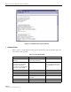


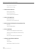


Table Of Contents
- SECTION 1: Overview
- SECTION 2: Description
- SECTION 3: Host Unit Installation
- SECTION 4: Operation
- SECTION 5: Maintenance
- SECTION 6: General Information
- ABOUT THIS MANUAL
- RELATED PUBLICATIONS
- ADMONISHMENTS
- GENERAL SAFETY PRECAUTIONS
- STANDARDS CERTIFICATION
- LIST OF ACRONYMS AND ABBREVIATIONS
- SECTION 1: Overview
- SECTION 2: Description

ADCP-75-116 • Issue A • August 2001 • Section 3: Host Unit Installation
Page 3-2
©
2001,
ADC
Telecommunications,
Inc.
Reverse
brackets
for
23-inch
racks
Provide
clearance
for
cooling
3 CHASSIS GROUND CONNECTION
Stud
on
rear
side
of
chassis
Use
#18
stranded
copper
wire
Connect
to
approved
earth
ground
source
4 COAXIAL CABLE CONNECTIONS
With
and
without
diversity
N-type
female
connectors
provided
on
unit
5 WAVE DIVISION MULTIPLEXER INSTALLATION (ACCESSORY ITEM)
Rack
mount
Chassis
and
WDM
module(s)
6 OPTICAL CONNECTIONS
Installations
with
the
WDM
(with
and
without
diversity
Installations
without
the
WDM
(with
and
without
diversity)
SC
connectors
Route
patch
cords
from
HU
to
fiber
distribution
panel
7 CONTROLLER AREA NETWORK CONNECTIONS
RJ-45
jacks
Cables
provided
Include
diagram
of
multiple
unit
connections