
User Manual


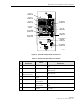


Table Of Contents
- SECTION 1: Overview
- SECTION 2: Description
- SECTION 3: Host Unit Installation
- SECTION 4: Operation
- SECTION 5: Maintenance
- SECTION 6: General Information
- ABOUT THIS MANUAL
- RELATED PUBLICATIONS
- ADMONISHMENTS
- GENERAL SAFETY PRECAUTIONS
- STANDARDS CERTIFICATION
- LIST OF ACRONYMS AND ABBREVIATIONS
- SECTION 1: Overview
- SECTION 2: Description

ADCP-75-116 • Issue A • August 2001 • Section 2: Description
Page 2-15
©
2001,
ADC
Telecommunications,
Inc.
Figure 2-6. Spectrum Transport Module User Interface
Table 2-3. Spectrum Transport Module User Interface
REF
NO
USER INTERFACE
DESIGNATION
DEVICE
FUNCTIONAL
DESCRIPTION
1PORT
1SC
connector Connection
point
for
the
forward
path
fiber
optic
link.
2PORT
2SC
connector Connection
point
for
the
reverse
path
primary
fiber
optic
link.
3PORT
3
(diversity
unit
only)
SC
connector Connection
point
for
the
reverse
path
diversity
fiber
optic
link.
4I/O On/Off
rocker
switch
Provides
AC
power
on/off
control.
5No
designation 3-wire
AC
power
cord
connector
Connection
point
for
the
AC
power
cord.
6No
designation 2-
wire
DC
power
cord
connector
Connection
point
for
the
battery
back-up
power
cord.
7 SERVICE DB-9
connector
(female)
Connection
point
for
the
RS-232
service
inter-
face
cable.
16801-A
(4) ON/OFF
SWITCH
(5) AC POWER
CONNECTOR
(6) DC POWER
CONNECTOR
(1) PORT 1
CONNECTOR
(2) PORT 2
CONNECTOR
(3) PORT 3
CONNECTOR
(7) SERVICE
CONNECTOR
(8-15) LED
INDICATORS
(16) ALARM
CONNECTOR
(17) DIVERSITY
ANTENNA
CONNECTOR
(18) ANTENNA
CONNECTOR