
User Manual

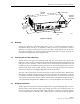


Table Of Contents
- SECTION 1: Overview
- SECTION 2: Description
- SECTION 3: Host Unit Installation
- SECTION 4: Operation
- SECTION 5: Maintenance
- SECTION 6: General Information
- ABOUT THIS MANUAL
- RELATED PUBLICATIONS
- ADMONISHMENTS
- GENERAL SAFETY PRECAUTIONS
- STANDARDS CERTIFICATION
- LIST OF ACRONYMS AND ABBREVIATIONS
- SECTION 1: Overview
- SECTION 2: Description

ADCP-75-116 • Issue A • August 2001 • Section 2: Description
Page 2-6
©
2001,
ADC
Telecommunications,
Inc.
3PRIMARY
PORT
2SC
connector Connection
point
for
the
reverse
path
primary
fiber
optic
link.
4 SECONDARY
PORT
3
SC
connector Connection
point
for
the
reverse
path
diversity
fiber
optic
link.
5 POWER Multi-colored
LED
(green/yellow)
Indicates
if
the
HU
is
powered
(green)
or
unpow-
ered
(off).
See
Note.
6 STANDBY Multi-colored
LED
(green/yellow/red)
Indicates
if
the
system
is
in
the
Normal
(off),
Standby
(blinking
green),
Test
(blinking
red),
or
Program
Load
(blinking
yellow)
state.
See
Note.
7 HOST
UNIT Multi-colored
LED
(green/yellow/red)
Indicates
if
the
HU
is
normal
(green)
overheated
(yellow)
or
faulty
(red).
See
Note.
8REMOTE
UNIT Multi-colored
LED
(green/yellow/red)
Indicates
if
the
RU
is
normal
(green)
or
faulty
(red).
See
Note.
9 OVERDRIVE Multi-colored
LED
(green/yellow/red)
Indicates
if
the
level
of
the
RF
input
signal
to
the
HU
is
normal
(green),
low
(yellow),
or
high
(red).
See
Note.
10 PORT
1/PORT
2 Multi-colored
LED
(green/yellow/red)
Indicates
if
the
primary
reverse
path
optical
sig-
nal
received
from
the
STM
is
normal
(green),
if
no
signal
is
detected
(red),
or
if
errors
are
detected
(red).
See
Note.
11 PORT
3
(diversity
unit
only)
Multi-colored
LED
(green/yellow/red)
Indicates
if
the
secondary
reverse
path
optical
signal
received
from
the
STM
is
normal
(green),
if
no
signal
is
detected
(red),
or
if
errors
are
detected
(red).
See
Note.
12 SERVICE DB-9
connector
(female)
Connection
point
for
the
RS-232
service
inter-
face
cable.
13 NET
IN RJ-45
jack
(female) Connection
point
for
the
CAN
interface
input
cable.
14 NET
OUT RJ-45
jack
(female) Connection
point
for
the
CAN
interface
output
cable.
15 ALARM
OUTPUT Screw-type
terminal
connector
(14–26
AWG)
Connection
point
for
an
external
alarm
system.
Includes
normally
open
(NO),
normally
closed
(NC),
and
common
(COM)
wiring
connections.
16 REVERSE
RF
OUT
N-type
female
RF
coaxial
connector
Connection
point
for
the
primary
reverse
path
RF
coaxial
cable.
17 REVERSE
2
RF
OUT
N-type
female
RF
coaxial
connector
Connection
point
for
the
diversity
reverse
path
RF
coaxial
cable.
18 FORWARD
RF
IN N-type
female
RF
coaxial
connector
Connection
point
for
the
forward
path
RF
coaxial
cable.
POWER
24–48
VDC
(Rear
side
-
not
shown)
Screw-type
terminal
strip
Connection
point
for
the
DC
power
wiring.
Note:
A
more
detailed
description
of
LED
operation
is
provided
in
Section
5.
Table 2-1. Host Unit User Interface, continued
REF
NO
USER INTERFACE
DESIGNATION
DEVICE
FUNCTIONAL
DESCRIPTION