
User Manual


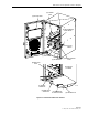
Table Of Contents
- SECTION 1: Overview
- SECTION 2: Description
- SECTION 3: Host Unit Installation
- SECTION 4: Operation
- SECTION 5: Maintenance
- SECTION 6: General Information
- ABOUT THIS MANUAL
- RELATED PUBLICATIONS
- ADMONISHMENTS
- GENERAL SAFETY PRECAUTIONS
- STANDARDS CERTIFICATION
- LIST OF ACRONYMS AND ABBREVIATIONS
- SECTION 1: Overview
- SECTION 2: Description

ADCP-75-116 • Issue A • August 2001 • Section 2: Description
Page 2-2
©
2001,
ADC
Telecommunications,
Inc.
6 DIGVANCE ELEMENT MANAGEMENT SYSTEM. . . . . . . . . . . . . . . . . . . . . . . . . . . . . . . . . . . . . . . . . . . . . . . . . . 2-19
6.1 Primary Components. . . . . . . . . . . . . . . . . . . . . . . . . . . . . . . . . . . . . . . . . . . . . . . . . . . . . . . . . . . . . 2-19
6.2 Service Interface Connection . . . . . . . . . . . . . . . . . . . . . . . . . . . . . . . . . . . . . . . . . . . . . . . . . . . . . . . 2-20
6.3 NOC Interface Connection . . . . . . . . . . . . . . . . . . . . . . . . . . . . . . . . . . . . . . . . . . . . . . . . . . . . . . . . . 2-20
6.4 EMS Software User Interface . . . . . . . . . . . . . . . . . . . . . . . . . . . . . . . . . . . . . . . . . . . . . . . . . . . . . . . 2-21
7 SPECIFICATIONS . . . . . . . . . . . . . . . . . . . . . . . . . . . . . . . . . . . . . . . . . . . . . . . . . . . . . . . . . . . . . . . . . . . . . 2-22
_________________________________________________________________________________________________________
1 INTRODUCTION
This
section
describes
the
basic
components
of
the
Digivance
LRCS
including
the
Host
Unit
(HU),
the
Remote
Unit
(RU),
and
the
Alarm
Network
Unit
(ANU).
Note
that
the
RU
is
actually
an
assembly
that
consists
of
a
cabinet,
a
Spectrum
Transport
Module
(STM),
and
a
Linear
Power
Amplifier
(LPA)
module.
For
clarity,
the
various
components
that
comprise
the
RU
are
described
separately.
2 HOST UNIT
The
HU,
shown
in
Figure 2-1,
serves
as
the
BTS
servicing
unit
for
the
Digivance
LRCS.
The
HU
provides
the
following
basic
functions:
• Provides
an
adjustable
RF
interface
with
the
BTS.
• Provides
an
optical
interface
with
the
RU.
• Digitizes
the
forward
path
composite
RF
signal.
•Converts
the
digitized
forward
path
RF
signal
to
a
digital
optical
signal.
•Converts
the
digitized
reverse
path
optical
signal
to
a
digitized
RF
signal.
•Converts
the
digitized
reverse
path
RF
signal
to
a
composite
RF
signal.
• Signals
alarm
information
to
an
external
alarm
system
through
relay
contact
closures
• Provides
an
RS-232
interface
for
a
local
or
remote
management
system.
• Provides
a
CAN
interface
for
networking
multiple
HUs.
2.1 Primary Components
The
HU
consists
of
an
electronic
circuit
board
assembly
and
a
fan
assembly
that
are
mounted
within
a
powder-coated
sheet
metal
enclosure.
The
enclosure
provides
a
mounting
point
for
the
circuit
board
and
fan
assemblies
and
controls
RF
emissions.
The
only
user-replaceable
component
is
the
fan
assembly.
The
HU
is
designed
for
use
within
a
non-condensing
indoor
environment
such
as
inside
a
wiring
closet
or
cabinet.
All
controls,
connectors,
and
indicators
(except
the
power
terminal
strip)
are
mounted
on
the
HU
front
panel
for
convenient
access.
Cable
management
functions
for
the
coaxial
and
fiber
optic
cables
are
provided
by
a
cable
management
tray
that
extends
outward
from
the
HU
front
panel.