
User Manual


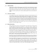
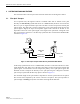


Table Of Contents
- SECTION 1: Overview
- SECTION 2: Description
- SECTION 3: Host Unit Installation
- SECTION 4: Operation
- SECTION 5: Maintenance
- SECTION 6: General Information
- ABOUT THIS MANUAL
- RELATED PUBLICATIONS
- ADMONISHMENTS
- GENERAL SAFETY PRECAUTIONS
- STANDARDS CERTIFICATION
- LIST OF ACRONYMS AND ABBREVIATIONS
- SECTION 1: Overview
- SECTION 2: Description

ADCP-75-116 • Issue A • August 2001 • Section 1: Overview
Page 1-1
©
2001,
ADC
Telecommunications,
Inc.
SECTION 1: OVERVIEW
1 INTRODUCTION. . . . . . . . . . . . . . . . . . . . . . . . . . . . . . . . . . . . . . . . . . . . . . . . . . . . . . . . . . . . . . . . . . . . . . . .1-1
2 SYSTEM OVERVIEW . . . . . . . . . . . . . . . . . . . . . . . . . . . . . . . . . . . . . . . . . . . . . . . . . . . . . . . . . . . . . . . . . . . .1-1
2.1 Basic Components. . . . . . . . . . . . . . . . . . . . . . . . . . . . . . . . . . . . . . . . . . . . . . . . . . . . . . . . . . . . . . . .1-1
2.2 Base Transceiver Station Interface . . . . . . . . . . . . . . . . . . . . . . . . . . . . . . . . . . . . . . . . . . . . . . . . . . . . .1-2
2.3 Handset Interface . . . . . . . . . . . . . . . . . . . . . . . . . . . . . . . . . . . . . . . . . . . . . . . . . . . . . . . . . . . . . . . .1-3
2.4 Local Service Interface. . . . . . . . . . . . . . . . . . . . . . . . . . . . . . . . . . . . . . . . . . . . . . . . . . . . . . . . . . . . .1-3
2.5 Remote NOC Interface . . . . . . . . . . . . . . . . . . . . . . . . . . . . . . . . . . . . . . . . . . . . . . . . . . . . . . . . . . . . .1-3
3 SYSTEM FUNCTIONS AND FEATURES . . . . . . . . . . . . . . . . . . . . . . . . . . . . . . . . . . . . . . . . . . . . . . . . . . . . . . . .1-4
3.1 Fiber Optic Transport . . . . . . . . . . . . . . . . . . . . . . . . . . . . . . . . . . . . . . . . . . . . . . . . . . . . . . . . . . . . . .1-4
3.2 Control and Monitoring Software . . . . . . . . . . . . . . . . . . . . . . . . . . . . . . . . . . . . . . . . . . . . . . . . . . . . . .1-6
3.3 Fault Detection and Alarm Reporting . . . . . . . . . . . . . . . . . . . . . . . . . . . . . . . . . . . . . . . . . . . . . . . . . . .1-6
3.4 Powering . . . . . . . . . . . . . . . . . . . . . . . . . . . . . . . . . . . . . . . . . . . . . . . . . . . . . . . . . . . . . . . . . . . . . .1-7
3.5 Equipment Mounting and Configuration . . . . . . . . . . . . . . . . . . . . . . . . . . . . . . . . . . . . . . . . . . . . . . . . .1-7
_________________________________________________________________________________________________________
1 INTRODUCTION
This
section
provides
basic
description,
application,
and
configuration
information
about
the
Digivance
SMR
800
MHz
Long
Range
Coverage
Solution
(LRCS).
Additional
versions
of
the
Digivance
LRCS
including
a
cellular
800
MHz
product
and
a
PCS
1900
MHz
product
are
planned
for
future
releases.
2 SYSTEM OVERVIEW
The
Digivance
SMR
800
MHz
LRCS
is
an
RF
signal
transport
system
that
provides
long-range
RF
coverage
in
areas
where
it
is
impractical
to
place
a
full
Base
Transceiver
Station
(BTS)
at
the
antenna
site.
High
real
estate
costs
and
community
restrictions
on
tower
and
equipment
locations
often
make
it
difficult
to
install
the
BTS
at
the
same
location
as
the
antenna.
The
Digivance
LRCS
is
designed
to
overcome
equipment
placement
problems
by
allowing
base
stations
to
be
hubbed
at
a
central
location
while
placing
remote
antennas
at
optimum
locations
with
minimal
real
estate
requirements.
With
the
Digivance
LRCS,
RF
signals
can
be
transported
to
one
or
more
remote
locations
to
expand
coverage
into
areas
not
receiving
service
or
to
extend
coverage
into
difficult
to
reach
areas
such
as
canyons,
tunnels,
or
underground
roadways.
2.1 Basic Components
The
basic
components
of
a
Digivance
LRCS
system
and
their
functions
are
shown
in
Figure 1-1.
One
link
of
a
basic
system
consists
of
the
Host
Unit
(HU)
and
the
Remote
Unit
(RU).
Control
and
monitoring
functions
are
provided
by
the
Digivance
Element
Management
System
(EMS).
On
an
optional
basis,
each
HU
and
RU
link
may
be
ordered
either
with
or
without
reverse
path
diversity.
In
addition,
two
accessory
items,
a
battery
back-up
kit
(for
the
RU)
and
a
Wave
Division
Multiplexer
(WDM)
module
(for
the
HU
and
RU)
are
available
if
required
by
the
application.