ADCP-75-110 Issue B March 2001 Digivance™ 800 Mhz Indoor Coverage Solution Installation and Operation Manual DRAFT 1126955 Rev A
ADCP-75-110 • Issue B • March 2001 COPYRIGHT 2001, ADC Telecommunications, Inc. All Rights Reserved Printed in the U.S.A. REVISION HISTORY ISSUE DATE REASON FOR CHANGE Issue B 03/01 Original TRADEMARK INFORMATION ADC and FiberGuide are registered trademarks of ADC Telecommunications, Inc. Digivance is a trademark of ADC Telecommunications, Inc. LC is a trademark of Lucent Technologies Inc. TORX is a registered trademark of Textron, Inc.
ADCP-75-110 • Issue B • March 2001 TABLE OF CONTENTS Content 1 2 Page SYSTEM FUNCTIONAL OVERVIEW AND UNIT DESCRIPTIONS ........................................ 1 1.1 System Functional Overview ....................................................... 1 1.2 Digital Host Unit Description ....................................................... 3 1.3 Digital Remote Unit Description ..................................................... 7 1.4 Digital Expansion Unit Description ...........................
ADCP-75-110 • Issue B • March 2001 TABLE OF CONTENTS Content 6 Page GENERAL INFORMATION ............................................................... 51 6.1 Warranty/Software ............................................................. 51 6.2 Software Service Agreement ....................................................... 51 6.3 Repair/Exchange Policy .......................................................... 51 6.4 Repair Charges ..............................................................
ADCP-75-110 • Issue B • March 2001 ABOUT THIS GUIDE This installation and operation manual provides the following information: • An overview of the Digivance Indoor Coverage Solution (ICS) and a description of the basic system components including the Digital Host Unit (DHU), Digital Expansion Unit (DEU), and the Digital Remote Unit (DRU). • System requirements for planning the Digivance ICS installation. • Procedures for installing the DHU.
ADCP-75-110 • Issue B • March 2001 ADMONISHMENTS Important safety admonishments are used throughout this manual to warn of possible hazards to persons or equipment. An admonishment identifies a possible hazard and then explains what may happen if the hazard is not avoided. The admonishments — in the form of Dangers, Warnings, and Cautions — must be followed at all times.
ADCP-75-110 • Issue B • March 2001 Danger: Always allow sufficient fiber length to permit routing without severe bends. Fibers may be permanently damaged if bent/curved to a radius of less than 1.5 inches (38 mm). STANDARDS CERTIFICATION FCC: This equipment complies with the applicable sections of Title 47 CFR Parts 15, 22, 24, and 90. UL/CUL: This equipment complies with UL and CUL 1950 Standard for Safety for Information Technology Equipment, Including Electrical Business Equipment.
ADCP-75-110 • Issue B • March 2001 RSSI RX TDMA TX UL UPS V VAC VDC WECO Page viii 2001, ADC Telecommunications, Inc.
ADCP-75-110 • Issue B • March 2001 1 SYSTEM FUNCTIONAL OVERVIEW AND UNIT DESCRIPTION This section provides an overview of the Digivance Indoor Coverage Solution (ICS), a description of the functions and features provided by the units that comprise the system, a listing of terms used and their definition, and a table of specifications. 1.
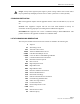
ADCP-75-110 • Issue B • March 2001 DRU DRU REMOTE BTS DRU DRU RIU DHU RF DRU LIU DRU DEU DRU RF LOCAL BTS DRU DEU DRU DRU DRU Fig 1C-A Figure 1. System Overview Functional Block Diagram 1.1.3 Interface With Cellular Phones The DRUs interface with the cellular phones. In the reverse path, the DRU receives RF signals from each cellular phone. The DRU digitizes the RF signals and then converts them to digital optical signals for transport to the DHU.
ADCP-75-110 • Issue B • March 2001 1.1.4 Digital Fiber Optic Transport The DHU is connected to each DRU unit over a pair of multi-mode fiber optic links. One link is used to transport the forward path optical signal. The other link is used to transport the reverse path optical signal. Because the optical signal is digital, no adjustments to the optical signal level are required at the DRU or the DHU regardless of the length of the optical link. Either 50 or 62.
ADCP-75-110 • Issue B • March 2001 • Distribution of the digitized forward path RF signals into six digitized optical signals • Conversion of up to six reverse path digitized optical signals to six digitized RF signals • Combining of the six digitized RF signals into a single composite digitized RF signal • Conversion of the combined digitized RF signal to a composite cellular RF signal • DC power for powering the DRUs • Relay contact closures to provide alarm information to an external alarm sy
ADCP-75-110 • Issue B • March 2001 1.2.3 Fault Detection and Alarm Reporting The DHU is designed to detect internal circuitry faults and optical port faults. Various front panel Light Emitting Diode (LED) indicators turn from green to red or yellow if a fault is detected. A set of alarm contacts (normally open and normally closed) are also provided for reporting an alarm to an external alarm system when a fault is detected.
ADCP-75-110 • Issue B • March 2001 (3) OPTICAL PORT LED INDICATOR (6 PLACES) (4) OPT/ELEC PORT ENABLE/DISABLE SWITCH (6 PLACES) (5) ELECTRICAL PORT DC POWER JACK (6 PLACES) (6) OPTICAL PORT OPTICAL ADAPTERS TX-LEFT - RX-RIGHT (6 PLACES) (2) AC POWER ON/OFF SWITCH (1) AC POWER CORD CONNECTOR NOTE: SHOWN WITHOUT CABLE MANAGEMENT TRAY (7) UNIT LED INDICATOR (10) RF INPUT CONNECTOR (9) ALARM (8) OVERDRIVE (11) RF OUTPUT TERMINAL LED CONNECTOR STRIP INDICATOR Fig 3B-A Figure 3.
ADCP-75-110 • Issue B • March 2001 1.3 Digital Remote Unit Description The DRU, shown in Figure 4, serves as the cellular user servicing unit for the Digivance ICS.
ADCP-75-110 • Issue B • March 2001 1.3.3 Fault Detection The DRU is designed to detect internal circuitry faults or loss of system inputs. A front panel LED indicator turns from green to red when a fault condition is detected or when the system optical input is lost. The DRU sends the fault information to the DHU over the fiber optic link. A corresponding port LED at the DHU turns red when the DRU reports a fault. 1.3.
ADCP-75-110 • Issue B • March 2001 (3) FIBER LINK (2) 48 VDC POWER OPTICAL ADAPTERS CONNECTOR TX-LEFT - RX-RIGHT FRONT VIEW REAR VIEW Fig 5B-A (1) STATUS LED (4) ANTENNA CONNECTOR Figure 5. Digital Remote Unit User Interface Table 2. Digital Remote Unit User Interface REF No. USER INTERFACE DESIGNATION DEVICE FUNCTIONAL DESCRIPTION 1 STATUS Multi-colored LED (Red/Green/Yellow) Indicates if the status of the DRU is normal or faulty or if the forward path optical input is normal or lost.
ADCP-75-110 • Issue B • March 2001 17.2 INCHES (437 mm) FRONT PANEL MOUNTING BRACKET (BOTH SIDES) 3.5 INCHES (89 mm) 11.4 INCHES (290 mm) 15.3 INCHES (389 mm) CABLE MANAGEMENT TRAY Fig 6B-A Figure 6. Digital Expansion Unit 1.4.1 Primary Components The DEU consists of two electronic circuit board assemblies that are mounted within a powder-coated sheet metal enclosure. The metal enclosure provides a mounting point for the electronic assemblies and serves as a heat sink.
ADCP-75-110 • Issue B • March 2001 1.4.4 Optical and Electrical Interface Connections Operation of the DRUs and DEUs is supported by six optical and six electrical ports. Each optical and electrical interface connection includes a status LED, a duplex LC type optical adapter, an RJ45 DC power jack, and a port enable/disable switch. An optical port may be connected to a DRU, a DEU, or not used. An electrical port may be connected to a DRU or not used.
ADCP-75-110 • Issue B • March 2001 Table 3. Digital Expansion Unit User Interface REF No.
ADCP-75-110 • Issue B • March 2001 TERM DEFINITION Digital Remote Unit The unit that interfaces the in-building user to the Digivance optical transport Digitized RF Signal The RF signal in a digitized form. Forward Path Signal A signal that travels from the base station to the cell phone. Major Alarm An alarm condition that applies when any fault (except high temperature) occurs. Minor Alarm The alarm condition that applies when a high temperature condition occurs.
ADCP-75-110 • Issue B • March 2001 Table 5. System Specifications (Continued) PARAMETER SPECIFICATION RF Forward Path System Bandwidth 25 MHz Frequency range Cellular: 869 to 894 MHz Output power +13 +/– 1 dB composite Gain variation +/– 3 dB Over frequency, temperature, and unitPer 1.25 MHz CDMA channel < 1.
ADCP-75-110 • Issue B • March 2001 Table 5. System Specifications (Continued) PARAMETER SPECIFICATION REMARKS Physical/Electrical - DEU Weight 17.5 lbs (7.9 kg) Optical connection Duplex LC adapter DC power connection RJ-45 Power source 120–240 VAC, 50–60 Hz Power consumption 22 W Current rating 85–250 VAC, 2 Amp input Physical/Electrical DRU Weight 2 lbs (0.
ADCP-75-110 • Issue B • March 2001 2 INSTALLATION PLANNING AND SYSTEM DESIGN This section provides installation planning information and basic system design recommendations for RF engineers that will be designing and installing an in-buildling coverage solution using the Digivance ICS. System design and planning services are available from ADC if required. Refer to section 6 of this manual for additional information. 2.
ADCP-75-110 • Issue B • March 2001 The LIU is rack or wall mountable and is powered by 120–240 VAC (50–60 Hz) power. Refer to the Digivance Local Interface Unit User Manual (ADCP-75-113) for a complete description of the LIU. 2.1.2 Remote BTS (Cell Site Base Station) Interface A remote interface between the DHU and the BTS (cell site base station) via a donor antenna requires specific RF input and output signal levels at the DHU and antenna.
ADCP-75-110 • Issue B • March 2001 2.2 Location and Mounting Requirements 2.2.1 DHU and DEU Location and Mounting Requirements The DHU and the DEU may be either rack mounted or wall mounted. Fasteners (both metric and US standard) are included with each unit for rack mount applications. A pair of reversible mounting brackets is provided that allows the unit to be mounted in either a 19-inch or 23-inch EIA or WECO equipment rack.
ADCP-75-110 • Issue B • March 2001 2.3 Powering Requirements 2.3.1 DHU and DEU Powering The DHU and DEU are powered by 120–240 VAC (50–60 Hz) which is supplied through a standard three-conductor AC power cord. The 120 VAC power cord is provided with the unit and is 98 inches (2.5 m) long. The DHU has a power consumption rating of 24 watts and the DEU has a power consumption rating of 22 watts. Locate each unit so that an AC outlet is within the reach of the power cord.
ADCP-75-110 • Issue B • March 2001 2.4 Optical Options and Requirements Each DHU and its associated DEUs and DRUs are connected over a pair of fiber optic links. One link transports the forward path optical signal and the other link transports the reverse path optical signal. Either 50 or 62.5 micron core multi-mode fiber optic cable may be used for the optical link. If 50 micron cable is used, the optical link may be up to 750 meters (2,460.75 ft) in length. If 62.
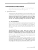
ADCP-75-110 • Issue B • March 2001 2.7 DRU Antenna Options Four antennas, shown in Figure 11, are available from ADC for use with the DRU. All antennas include a 6 foot (1.8 m) long 50-ohm coaxial cable (equipped with SMA male connector) for connection to the DRU. The DRU is equipped with an SMA female connector for connecting the antenna cable. The DRU antennas are designed for unobtrusive mounting within an office environment.
ADCP-75-110 • Issue B • March 2001 2.8 Local Alarm System Reporting Requirements The DHU provides normally open (NO) and normally closed (NC) dry alarm contacts for reporting minor and major alarms to an external alarm system. A minor alarm is defined as a high temperature condition. A major alarm is defined as any fault condition except high temperature. Connections to the alarm contacts are provided through a screw-type terminal strip. Use #26 AWG insulated solid copper wire for the alarm wires.
ADCP-75-110 • Issue B • March 2001 Determine the Amount of Building Attenuation: If a donor antenna will provide the RF link to the BTS, determine if there is enough signal isolation between the donor antenna and the inbuilding system to avoid a feedback loop and signal degradation. This step can often be accomplished during the preliminary walkthrough.