
User Manual


ADCP-75-110 • Issue 2B • July 2001
Page 35
©
2001,
ADC
Telecommunications,
Inc.
16429-B
REVERSE PATH (RX)
CONNECTOR
FORWARD PATH (TX)
CONNECTOR
OPTICAL CONNECTOR
ASSEMBLY DETAIL
PORT 1
OPTICAL
TRANSCEIVER
OPTICAL
CONNECTOR
CABLE
GUIDES
CABLE GUIDE
DETAIL
DESIGNATION CARD AND
HOLDER DETAIL
HOLDER
CARD
CLEAR
PLASTIC
COVER
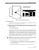
Figure 20. Ports 1–6 Fiber Optic Cable Connections
9.
Place
the
optical
fibers
within
the
cable
guides
provided
on
the
cable
management
tray
(see
Figure
20)
and
then
dress
and
secure
the
fibers
at
the
DHU
per
standard
industry
practice.
10.
Connect
the
forward
and
reverse
path
optical
fibers
to
the
DEU
or
the
DRU
as
specified
in
the
instructions
provided
with
that
unit.
11.
Use
the
designation
card
provided
(see
Figure
20)
to
indicate
the
location
and
name
of
the
DRU
or
DEU
that
is
connected
to
the
optical
fibers.
The
designation
card
holder
may
be
attached
to
any
convenient
flat
surface
such
as
the
DHU
cable
management
tray
12.
Repeat
steps
1–11
for
each
remaining
optical
port.
3.9 DC Power Connections
The
DC
power
interface
between
the
DHU
and
each
DRU
is
supported
by
six
RJ-45
female
connectors.
Each
DHU
RJ-45
connector
provides
nominal
48
Vdc
power
for
the
associated
DRU
except
when
the
DRU
is
powered
with
an
ac/dc
converter.
A
category
3
or
5
twisted
pair
cable
is
used
to
feed
the
power
from
the
DHU
to
the
DRU.
Use
the
following
procedure
to
install
the
DC
power
cable
and
to
connect
it
to
the
DHU.
1.
Obtain
the
required
length
of
category
3
or
5
twisted
pair
cable.
2.
Route
the
cable
between
the
DHU
and
the
DRU
(unless
already
routed)
and
then
cut
to
required
length.
Allow
sufficient
slack
for
dressing
and
organizing
the
cable
at
the
DHU.
Note:
The
maximum
distance
for
routing
power
cable
is
500
meters
(1,641
feet).