
User Manual


ADCP-75-110 • Issue 2B • July 2001
Page 34
©
2001,
ADC
Telecommunications,
Inc.
3.8 Ports 1–6 Optical Connections
The
optical
interface
between
the
DHU
and
each
DEU
or
DRU
is
supported
by
six
optical
ports.
Each
of
the
six
optical
ports
provides
a
duplex
LC
type
optical
transceiver
which
is
mounted
on
the
DHU
front
panel.
One
side
of
the
transceiver
provides
the
optical
fiber
connection
for
the
forward
path
(downlink)
signal.
The
other
side
of
the
transceiver
provides
the
optical
fiber
connection
for
the
reverse
path
(uplink)
signal.
Use
the
following
procedure
to
install
the
forward
and
reverse
path
optical
fibers
and
to
connect
them
to
the
DHU:
Danger:
This
equipment
uses
a
Class
1
Laser
according
to
FDA/CDRH
rules.
Laser
radiation
can
seriously
damage
the
retina
of
the
eye.
Do
not
look
into
the
ends
of
any
optical
fiber.
Do
not
look
directly
into
the
optical
transceiver
of
any
digital
unit
or
exposure
to
laser
radiation
may
result.
An
optical
power
meter
should
be
used
to
verify
active
fibers.
A
protective
cap
or
hood
MUST
be
immediately
placed
over
any
radiating
transceiver
or
optical
fiber
connector
to
avoid
the
potential
of
dangerous
amounts
of
radiation
exposure.
This
practice
also
prevents
dirt
particles
from
entering
the
transceiver
or
connector.
1.
Obtain
the
required
lengths
of
50
or
62.5
micron
core
multi-mode
fiber
optic
cable.
2.
Route
the
fiber
optic
cable
between
the
DHU
and
the
DEU
or
DRU
(if
not
already
routed)
and
cut
to
required
length.
Allow
sufficient
slack
for
dressing
and
organizing
the
cables
at
each
unit.
Maintain
a
minimum
bend
radius
of
2
inches
(50
mm).
Note:
The
maximum
distance
for
routing
50
micron
core
fiber
optic
cable
is
750
meters
(2,461
feet).
The
maximum
distance
for
routing
62.5
micron
core
fiber
optic
cable
is
500
meters
(1,641
feet).
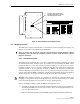
3.
Terminate
each
optical
fiber
with
a
field-installable
LC
type
fiber
optic
connector
as
shown
in
Figure
20.
Follow
the
instructions
provided
by
the
connector
manufacturer
for
installing
the
connector.
4.
Test
each
fiber
for
optical
loss
as
described
in
Subsection
5.4.2
of
this
manual.
5.
Designate
one
of
the
fibers
as
the
forward
path
link
and
the
other
as
the
reverse
path
link
and
attach
an
identification
tag
to
each
fiber
end
next
to
the
connector.
6.
Use
the
plastic
joiner
provided
with
the
LC
connectors
to
join
the
DHU
Port
1
forward
and
reverse
path
connectors
together
(see
Figure
20).
Make
sure
the
forward
path
and
reverse
path
connectors
are
oriented
as
shown.
Note:
When
viewing
any
Port
1-6
optical
transceiver
from
the
front,
the
forward
path
port
is
on
the
left
and
the
reverse
path
port
is
on
the
right.
7.
Remove
the
dust
caps
from
the
optical
fiber
connectors
and
the
port
1
optical
transceiver.
Note:
Leave
the
dust
cap
in
place
on
any
unused
optical
port.
8.
Clean
each
connector
(follow
connector
supplier’s
recommendations)
and
then
insert
the
optical
link
connector
pair
into
DHU
optical
port
1
(see
Figure
20).