
User Manual


ADCP-75-110 • Issue 2B • July 2001
Page 32
©
2001,
ADC
Telecommunications,
Inc.
4.
Set
the
DHU
aside
and
then
drill
appropriately
sized
holes
in
the
mounting
surface
for
the
fasteners.
5.
Partially
install
the
fasteners
in
the
drilled
holes.
Leave
the
head
of
each
fastener
protruding
about
1/4
inch
(6
mm)
from
the
mounting
surface.
6.
Hang
the
DHU
from
the
fasteners
and
then
securely
tighten
each
fastener.
3.6 Chassis Ground Connection
A
stud
is
provided
on
the
rear
side
of
the
chassis
for
connecting
a
grounding
wire
to
the
chassis.
Use
the
following
procedure
to
connect
the
grounding
wire
to
the
chassis
and
to
route
the
grounding
wire
to
an
approved
earth
ground
source:
1.
Obtain
a
length
of
#18
AWG
(1.00
mm)
insulated
stranded
copper
wire
for
use
as
a
chassis
grounding
wire.
2.
Terminate
one
end
of
the
wire
with
a
ring
terminal.
3.
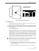
Locate
the
chassis
ground
stud
at
the
rear
of
the
DHU
as
shown
in
Figure
18.
16169-A
Figure 18. Chassis Ground Stud
4.
Attach
the
ring
end
of
the
wire
to
the
chassis
ground
stud
(see
Figure
18).
5.
Route
the
free
end
of
the
chassis
grounding
wire
to
an
approved
(per
local
code
or
practice)
earth
ground
source.
6.
Cut
the
chassis
grounding
wire
to
length
and
connect
it
to
the
approved
ground
source
as
required
by
local
code
or
practice.
Note:
Be
sure
to
maintain
reliable
grounding
for
rack
and
wall
mounted
equipment.
Pay
particular
attention
to
ground
source
connections.