
User Manual


ADCP-75-110 • Issue 2B • July 2001
Page 29
©
2001,
ADC
Telecommunications,
Inc.
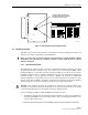
ALIGN DIP SWITCH HANDLES AS
SHOWN ON THE LABEL TO PROVIDE
SPECIFIED FREQUENCY BAND
Fig 13-A
Figure 14. 1900 MHz DHU Frequency Band Selection
3.5 Mounting Procedure
The
DHU
may
be
either
rack-mounted
or
wall-mounted.
Of
the
procedures
that
follow,
use
which
ever
procedure
is
appropriate
for
the
installation:
Note:
To
insure
that
all
optical
connectors
and
transceivers
remain
dust-free
during
installation,
leave
all
dust
caps
and
dust
protectors
in
place
until
directed
to
remove
them
for
connection.
3.5.1 Rack Mount Installation
The
DHU
may
be
mounted
in
either
a
19-inch
or
23-inch
EIA
or
WECO
equipment
rack.
Both
US
standard
and
metric
machine
screws
are
included
for
rack
mounting
the
DHU.
When
loading
the
DHU
in
a
rack,
make
sure
the
mechanical
loading
of
the
rack
is
even
to
avoid
a
hazardous
condition
such
as
a
severely
unbalanced
rack.
The
rack
should
safely
support
the
combined
weight
of
all
the
equipment
it
holds.
In
addition,
the
maximum
recommended
ambient
temperature
for
the
DHU
is
50º
C
(122º
F).
Allow
sufficient
air
circulation
or
space
between
units
when
the
DHU
is
installed
in
a
multi-unit
rack
assembly
because
the
operating
ambient
temperature
of
the
rack
environment
might
be
greater
than
room
ambient.
Warning:
Wet
conditions
increase
the
potential
for
receiving
an
electrical
shock
when
installing
or
using
electrically-powered
equipment.
To
prevent
electrical
shock,
never
install
or
use
electrical
equipment
in
a
wet
location
or
during
a
lightning
storm.
Use
the
following
procedure
to
install
the
DHU
in
the
equipment
rack:
1.
The
DHU
is
shipped
with
the
mounting
brackets
installed
for
19-inch
rack
installations.
If
mounting
the
DHU
in
a
19-inch
rack,
proceed
to
step
4.
If
mounting
the
DHU
in
a
23-
inch
rack,
proceed
to
step
2.
2.
Remove
both
mounting
brackets
from
the
DHU
(requires
TORX
screwdriver
with
T20
bit)