
User Manual


ADCP-75-110 • Issue 2B • July 2001
Page 28
©
2001,
ADC
Telecommunications,
Inc.
The
following
materials
are
required
in
order
to
complete
the
procedures
in
this
section:
• Wall-mount
fasteners
(wall-mount
applications
only)
• #22
AWG
(0.40
mm)
category
3
or
5
cable
(for
power
cable
and
external
alarm
connections)
• RJ-45
male
connectors
(for
power
cable)
• #18
AWG
(1.00
mm)
insulated
stranded
copper
wire
(for
chassis
grounding
wire)
• Ring
terminal
for
#18
wire
(for
chassis
ground
wire
connection)
• 50
or
62.5
micron
core
multi-mode
fiber
optic
cable
• LC-type
field
installable
connectors
• High
performance,
flexible,
low
loss
50-ohm
coaxial
cable
• N-type
male
connectors
• Wire
ties
3.3 Unpacking and Inspection
This
subsection
provides
instructions
for
opening
the
shipping
boxes,
verifying
that
all
parts
have
been
received,
and
verifying
that
no
shipping
damage
has
occurred.
Use
the
following
procedure
to
unpack
and
inspect
the
DHU:
1.
Open
the
shipping
carton
and
carefully
unpack
the
DHU
from
the
protective
packing
material.
2.
Check
the
DHU
for
broken
or
missing
parts.
If
there
are
any
damages,
contact
ADC
(see
Section
6
at
the
end
of
this
manual)
for
an
RMA
(Return
Material
Authorization)
and
to
reorder
if
replacement
is
required.
3.4 Frequency Band Selection Procedure (1900 MHz DHU only)
The
1900
MHz
version
of
the
DHU
may
be
configured
to
operate
at
any
one
of
four
frequency
bands.
A
DIP
switch
is
provided
on
the
underside
of
the
DHU
for
selecting
the
required
frequency
band.
Use
the
following
procedure
to
set
the
DIP
switch
to
provide
the
required
1900
MHz
frequency
band:
1.
Determine
the
required
frequency
band
for
the
DHU
(AD,
DBE,
BEF,
or
EFC)
as
specified
in
the
system
design
plan.
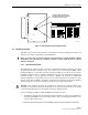
2.
Orient
the
DHU
as
shown
in
Figure
14
and
then
locate
the
small
hole
in
the
bottom
of
the
DHU
that
provides
access
to
the
band
select
DIP
switch.
3.
Use
a
non-conductive
probe
to
align
the
DIP
switch
sliding
handles
to
provide
the
required
frequency
band
(see
Figure
14).
4.
Place
the
copper
sticker
provided
with
the
DHU
over
the
small
opening
that
provides
access
to
the
DIP
switch.
Note:
The
copper
sticker
provides
EMI/RFI
shielding.
Do
not
use
some
other
type
of
material
to
cover
the
DIP
switch
access
hole.