
User Manual


ADCP-75-110 • Issue 2B • July 2001
Page 36
©
2001,
ADC
Telecommunications,
Inc.
3.
Terminate
each
end
of
the
cable
with
a
male
RJ-45
connector.
Match
the
wire
color
to
the
connector
pin
as
specified
in
Table
6.
Caution:
The
DRU
will
be
damaged
if
the
RJ-45
connector
is
wired
incorrectly.
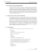
Table 6. RJ-45 Connector Pin Designations
PIN NUMBER WIRE COLOR CONNECTOR PINS
1
2
3
4
5
6
7
8
White/Green
Green
White/Orange
Orange
White/Blue
Blue
White/Brown
Brown
PIN
1
PIN
8
+48 VDC ON PINS 1, 3, 5, AND 7
RETURN ON PINS 2, 4, 6, AND 8
16180-A
4.
Perform
a
continuity
test
to
verify
that
each
wire
is
properly
connected
to
the
terminating
RJ-45
connector
and
check
the
connector
for
correct
polarity
(see
diagram
in
Table
6).
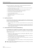
5.
Connect
the
DC
power
cable
to
the
DHU
port
1
DC
PWR
jack
as
shown
in
Figure
21.
16430-A
RJ-45 CONNECTOR
DETAIL
PORT 1
DC POWER
CONNECTOR
RJ-45
CONNECTOR
CABLE
GUIDES
CABLE GUIDE
DETAIL
1
8
Figure 21. 48 Vdc Power Cable Connection