
Installation Manual


ADCP-75-112 • Issue 2A • June 2001
Page 9
©
2001,
ADC
Telecommunications,
Inc.
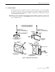
2.4 DRU Mounting Procedure
The
DRU
may
be
mounted
on
any
flat
vertical
or
horizontal
surface.
A
slot
is
provided
in
each
of
the
four
mounting
feet
for
inserting
a
fastener.
The
fasteners
must
be
provided
by
the
installer.
Use
the
following
procedure
to
mount
the
DRU:
Warning:
Wet
conditions
increase
the
potential
for
receiving
an
electrical
shock
when
installing
or
using
electrically-powered
equipment.
To
prevent
electrical
shock,
never
install
or
use
electrical
equipment
in
a
wet
location
or
during
a
lightning
storm.
Note:
To
insure
that
all
optical
connectors
and
transceivers
remain
dust-free
during
installation,
leave
all
dust
caps
and
dust
protectors
in
place
until
directed
to
remove
them
for
connection.
1. Obtain
the
appropriate
fasteners
(lag
bolts,
screws,
wall
anchors,
etc.)
for
securing
the
DRU
to
the
mounting
surface.
2. Position
the
DRU
on
the
mounting
surface
in
the
specified
location
(per
the
system
design).
Make
sure
the
LED
will
be
visible
when
the
unit
is
mounted.
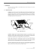
Note:
To
ensure
there
is
adequate
air
circulation
for
cooling,
provide
a
minimum
of
3
inches
(76
mm)
of
clearance
space
on
all
sides
of
the
DRU
(except
the
bottom).
In
addition,
at
least
one
surface
of
the
DRU
installation
area
must
be
open
to
the
building’s
interior
air
space.
If
a
portable/flexible
antenna
will
be
installed,
allow
a
minimum
of
9
inches
(229
mm)
clearance
along
the
surface
with
the
antenna.
Note:
In
mounting
situations
where
fiber,
power,
and
coaxial
cable
pass-through
holes
are
planned,
it
is
critical
that
these
holes
be
placed
far
enough
away
from
their
respective
connectors
to
avoid
forming
overly
tight
bend
radii.
Tight
bend
radii
can
damage
fiber
optic
cable
and
reduce
RF
signal
levels.
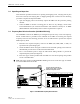
The
DRU
mounting
template
(part
#
1154319)
provides
the
clearances
for
the
following
cable
types:
Power
cable
(cat
3
and
5): 0.2
inch
(5.2
mm)
diameter
Fiber
optic
cable
(twin
lead): 0.12
inch
(3.0
mm)
diameter
Antenna
coaxial
cable: 0.16
inch
(4.0
mm)
diameter
If
planned
cable
diameters
are
greater
than
those
listed,
please
consult
with
the
cable
manufacturer
to
determine
the
cable’s
recommended
minimum
bend
radii.
3. Mark
the
location
of
the
mounting
holes
and
of
any
pass-through
holes
that
may
be
required
for
fiber,
power,
or
coaxial
cables.
Observe
any
additional
instructions
that
may
be
printed
on
the
template
such
as
the
recommended
fasteners
and
clearance
requirements.
4. Drill
appropriately
sized
holes
in
the
mounting
surface
for
the
mounting
screws
or
wall
anchors
and
for
the
fiber,
power,
or
coaxial
cables
(if
pass-through
holes
are
required).
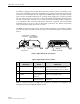
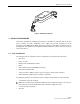
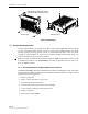
5. Place
the
DRU
in
position
for
mounting
and
then
install
the
fasteners
as
shown
in
Figure
7.
6. Securely
tighten
each
fastener.