
Installation Manual


ADCP-75-112 • Issue 2A • June 2001
Page 4
©
2001,
ADC
Telecommunications,
Inc.
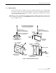
The
DRU
is
equipped
with
a
female
RJ-45
jack
that
provides
a
point
for
connecting
a
DC
power
cable.
The
DRU
is
powered
by
34–48
Vdc
power
which
is
supplied
through
the
RJ-45
connector.
Power
to
the
DRU
may
be
supplied
by
the
DHU,
DEU,
or
by
a
120
Vac
to
48
Vdc
power
converter
(available
separately
as
an
accessory
item)
plugged
into
a
properly
grounded
120
Vac
outlet.
The
AC/DC
converter
is
a
UL
Listed
stand
alone
Limited
Power
Supply
(LPS)
unit
with
a
rated
output
of
48
Vdc
at
1.2
A.
When
powered
by
the
DHU
or
DEU,
a
category
3
or
5
twisted-pair
cable
terminated
with
RJ-45
connectors
is
required.
The
recommended
maximum
length
of
the
power
cable
is
500
meters
(1,641
feet).
Any
distance
beyond
500
meters
requires
powering
by
the
AC/DC
converter.
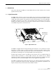
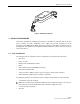
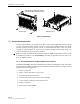
The
DRU
user
interface
consists
of
the
connectors
and
the
LED
that
are
provided
on
the
DRU
front
and
rear
panels.
The
DRU
user
interface
points
are
indicated
in
Figure
2
and
described
in
Table
1.
16421-A
REAR VIEWFRONT VIEW
(4) ANTENNA CONNECTOR
(1) STATUS LED
(2) 48 VDC POWER
CONNECTOR
(3) FIBER LINK
OPTICAL ADAPTERS
TX-LEFT - RX-RIGHT
Figure 2. Digital Remote Unit User Interface
Table 1. Digital Remote Unit User Interface
REF
No.
USER INTERFACE
DESIGNATION DEVICE
FUNCTIONAL
DESCRIPTION
1 STATUS Multi-colored
LED
(Red/Green/Yellow)
Indicates
if
the
status
of
the
DRU
is
normal
or
faulty
or
if
the
forward
path
optical
input
is
normal
or
lost.
(see
Note)
248
Vdc RJ-45
jack
(female) Used
for
connecting
a
DC
power
cable.
3 FIBER
TX
RX
Small
form
factor
LC-type
optical
transceiver
Used
for
connecting
the
forward
path
and
reverse
path
optical
links.
4 – SMA-type
coaxial
connector
(female)
Used
for
connecting
the
antenna
coaxial
cable
lead.
Note:
A
detailed
description
of
DEU
LED
operation
is
provided
in
the
Digivance
ICS
Installation
and
Operation
Manual
(ADCP-75-110)