
User's Manual


ADCP-75-187 • Issue 1 • September 2005 • Section 3: OPERATION
Page 3-3
© 2005, ADC Telecommunications, Inc.
2.1 Turn-Up Procedure
Each Digivance system must be turned-up separately before being networked together with
multiple systems through the CAN interface. Use the following procedure to turn-up each
Digivance system:
1. Temporarily disconnect the external alarm system or notify the alarm system provider that
testing is in progress.
2. If the HU is networked together with multiple HU’s, temporarily disconnect the CAN cables
from the NET IN and NET OUT ports of the HU.
3. Determine if the forward path composite input signal level at the host unit RF IN port(s) is
appropriate to produce the required RF output signal level. Note that 800/900 MHz SMR
host units have two forward path RF ports. Adjust by installing an external attenuator if
necessary. For adjustment purposes, the optimum input signal level is –20 dBm for 800/
900 MHz SMR systems. Refer to Section 2.2 for the calculation and adjustment procedure.
4. At the HU: Place the ON/OFF switch on the HU in the ON position (press I).
5. At the RU: Place the AC circuit breaker switch in the closed (ON) position.
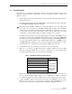
6. Wait 6 to 10 seconds for the HU and the RU to initialize and then observe the LED
indicators on the HU and RU. Refer to Section 4: Maintenance for the troubleshooting
procedures if the indicators do not respond as specified in Table 3-1.
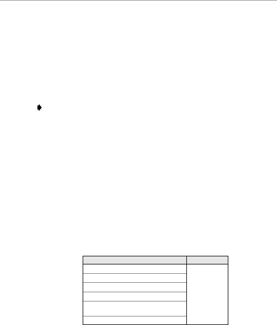
Table 3-1. LED Indicator Operation at Initial Turn-Up
7. Measure the input optical power level at the HU and RU and verify that the optical power
level received at the HU and RU is within –15 to –25 dBm with –17 dBm recommended
for commissioning. Refer to Section 4: Maintenance for the optical power test procedure.
8. Connect the EMS computer (if not already connected) to the SERVICE connector on the
HU front panel. If necessary, a separate laptop computer loaded with EMS Version 3.01
software can be temporarily connected and used to initially configure the system.
Note: By default, all HU’s and RU’s are programmed with the same site number and
name. This can cause problems for the EMS if multiple HU’s with the same site number
and site name are networked together through the CAN interface. It is therefore necessary
to temporarily disconnect the CAN interface cables from the HU when it is being
configured for operation until a unique site number and name can be assigned.
REAR ACCESS HOST UNIT REMOTE UNIT
POWER – Green
No LED desig-
nation – Off
Note: This LED
will stay red for
6 to 10 seconds
while the RU
initializes and
then turn off.
STANDBY – Off
HOST UNIT – Green
REMOTE UNIT – Green
DRIVE 851–869 – Green, Yellow, or Red
DRIVE 935–940 – Green, Yellow, or Red
FWD/REV (PORT 1/PORT 2) – Green