
User's Manual


ADCP-75-210 • Issue 1 • November 2006
Page 11
© 2006, ADC Telecommunications, Inc.
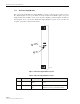
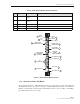
Figure 7 is a schematic showing the data flow in the RAN chassis. As shown, data flows in two
directions, from the Hub through the RAN to the antenna, and from the antenna through the
RAN back to the Hub. In each direction, data conversion occurs, with optical data
“upconverted” to RF data in the up direction in the schematic, and RF data “downconverted” to
optical data in the down direction. In an up direction, the RUC module converts Digitized
Intermediate Frequency (DIF) data into PCS, Cellular, and SMR frequency RF bands. The RF
signals are amplified and then transmitted from the RF antenna. In the down direction, the RDC
module converts PCS, Cellular, and SMR frequency bands into DIF data. The overall series of
events is managed by the CPU using an Ethernet connection to the chassis backplane.
Figure 7. RAN Chassis Schematic
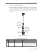
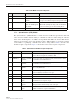
5 Small Form-Factor Pluggable Optical Transceiver (SFP) Section 1.7.5 on Page 17
6 RAN Down Converter (RDC or RDC2) Section 1.7.6 on Page 17
7 RAN Up Converter (RUC2.X or RUC3) Section 1.7.7 on Page 19
8 800 MHz Multi-Coupler Section 1.7.9 on Page 20
9 1900 MHz Multi-Coupler Section 1.7.10 on Page 22
10 Fan Access Panel Section 1.7.8 on Page 20
Table 3. RAN Chassis Electronic Modules
REF # MODULE NAME FOR DETAILS REFER TO
SIF
MPLX
RF RF
Pri Div
Pri Div Pri Div
1900
MUL
800
MUL
DIF
DIF
RF
1900-P 1900-D 800-P 800-D
DIF
RUC RDC
CPU
Ethernet
Fiber Fiber
6 6 3 3
MCPA
RAN
HUB
MB
ANT
RAN = Radio Access Node
DIF = Digital Intermediate
Frequency
SIF = Synchronous Interface
RUC = RAN Up Converter
MCPA = Munti-Carrier Power
Amplifier
MPLX = Multi-plexer/Combiner
MB ANT = Multi Band Antenna
MUL = Multi-Coupler
RDC = RAN Down Converter
21294-A