
User's Manual


ADCP-75-210 • Issue 1 • November 2006
Page 26
© 2006, ADC Telecommunications, Inc.
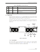
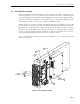
1.10 Multiplexer System
The NXD RAN multiplexer system consists of four units that interface to the antenna, PAs, and
multicouplers. There are four types found in found in every RAN:
• Quadplexer Primary (PCS Bands A, B, F), interfaces to PCS primary antenna;
• Quadplexer Diversity (PCS Bands D, E, C), interfaces to PCS diversity antenna;
• Triplexer Primary (Cellular Band B, SMR800 band), interfaces to 800 MHz primary
antenna;
• Diplexer Diversity (Cellular Band A), interfaces to 800 MHz diversity antenna.
For a schematic of the PCS multiplexers, see Figure 21. For a schematic of the Cellular/SMR
multiplexers, see Figure 22.
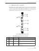
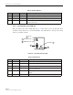
Table 14. PAA Connection Points and Indicators
REF # DESIGNATION DEVICE FUNCTIONAL DESCRIPTION
1 DC_IN Green LED DC In. Lighted when PIC has -48 VDC input
2 PA_FAULT Red LED PA Fault. Lighted when PA has failed
3 DC_OUT Green LED DC Out. Lighted when PIC has +28 VDC output
4 I2C RJ-45 connector
(J1)
I2C (Bus). Connection to RUC module P/A CNTRL using
cable 1001475P001
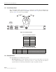
5 48V PWR Positronic 3-pin
connector (J2)
48 Volt DC Power. Input to PIC for -48 VDC using PIC
power harness 1001471P001
6 RF OUT SMA connector RF Out. Output of PA for cable 1955000P080 to one of the
four plexers (depending on band), connector port TX
7 (Unmarked) Power Amplifier Power amplifier (see description on preceding page)
8 RF IN SMA connector RF In. Input from RUC for cable 19559999P079