
User Manual


ADCP-75-179 • Preliminary Issue A • September 2004 • Section 3: Operation
Page 3-14
© 2004, ADC Telecommunications, Inc.
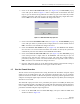
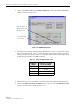
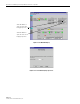
1. Click on the REMOTE RF tab. The REMOTE RF display will open within the EMS main
window as shown in Figure 3-10.
Figure 3-10. REMOTE LPA Display
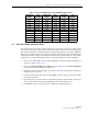
2. Check the level of the RF output signal (as determined in Section 2.6) against the system
design plan specifications. Table 3-2 shows the output signal level required to provide 5
watts per channel for systems with 1 to 4 channels. The maximum output signal level
permitted for the system is 43.4 dBm (22 Watts).
3. Determine if more or less attenuation is required to produce the required output signal level.
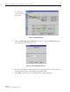
4. Click on the Remote Fwd Att field Edit button (see Figure 3-10). The Remote Fwd Att
pop-up screen will open as shown in Figure 3-11.
Table 3-2. Composite Output Signal Levels
NUMBER OF
CHANNELS
OUTPUT SIGNAL LEVEL
REQUIRED TO PROVIDE 5
WATTS PER CHANNEL
137 dBm
240 dBm
342 dBm
443 dBm
Click Edit button to
open the Remote Fwd
Att pop-up screen
RF output signal
level (± 3 dB)