
User Manual


ADCP-75-179 • Preliminary Issue A • September 2004 • Section 3: Operation
Page 3-12
© 2004, ADC Telecommunications, Inc.
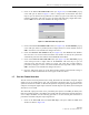
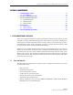
Figure 3-8. HOST RF Display
2. Click on the Host Fwd Att Edit button (see Figure 3-8). The Host Fwd Att pop-up screen
will open as shown in Figure 3-9.
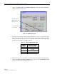
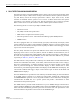
Figure 3-9. Host Fwd Att Pop-Up Screen
3. Obtain the value of the total composite input signal level as determined in step 11 of
Section 2.3.
4. Determine the appropriate value to enter for the Host forward path attenuator by
subtracting the required system output level (per system design plan) from the system gain
(85 dB) and then adding the composite input signal level. The result (see sample
calculation) is the amount of attenuation required.
Atten = (System Gain) – (Required System Output Power) + (Composite Input Power)
5. Enter the attenuation value and click OK to close the pop-up screen and to make the
changes take effect.
Click on Edit button
to open Host Fwd
Att pop-up screen