
User Manual


ADCP-75-159 • Issue 1 • August 2003 • Section 2: Description
Page 2-20
© 2003, ADC Telecommunications, Inc.
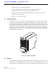
6 LINEAR POWER AMPLIFIER
The Linear Power Amplifier (LPA), shown in Figure 2-9, works in conjunction with the STM to
amplify the forward path RF output signal. The STM is interfaced with the LPA through the
D-sub connectors and wiring harness located at the rear of the RU cabinet or RU mounting
shelf. The RF signal is passed to the LPA for amplification and then passed back to the STM for
filtering and output via the STM’s ANTENNA port. The STM also supplies DC power to the
LPA through the same interface.
6.1 Primary Components
The LPA consists of a fan and several electronic circuit board assemblies that are mounted
within a powder-paint coated sheet metal enclosure. The metal enclosure provides a mounting
point for the electronic components and also controls RF emissions. Except for the fan unit, the
electronic components are not user replaceable. The LPA is designed for use within the RU
outdoor cabinet or RU indoor mounting shelf. Except for the STM interface connector, all
controls, indicators, and switches are mounted on the LPA front panel for easy access. A
carrying handle is provided on the front of the LPA to facilitate installation and transport.
Figure 2-9. Linear Power Amplifier
6.2 Mounting
The LPA mounts within the RU outdoor cabinet or RU indoor mounting shelf. Runners on the
top and bottom of the LPA mesh with tracks. The runners and tracks guide the LPA into the
installed position. The electrical interface between the STM and LPA is supported by a D-sub
female connector located on the rear side of the LPA. A corresponding D-sub male connector
mounted at the rear of the RU outdoor cabinet or RU indoor mounting shelf mates with the LPA
connector. Captive screws are provided for securing the LPA in the installed position.
18764-A