
User Manual


ADCP-75-159 • Issue 1 • August 2003 • Section 2: Description
Page 2-19
© 2003, ADC Telecommunications, Inc.
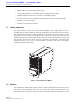
Figure 2-8. Spectrum Transport Module User Interface
10 STM Multi-colored LED
(green/yellow/red)
Indicates if the STM is normal (green) or faulty
(red). See Note.
11 PA Multi-colored LED
(green/yellow/red)
Indicates if the power amplifier is normal
(green), over temperature (yellow), has a fan fail-
ure (yellow), or is faulty (red). See Note.
12 VSWR Multi-colored LED
(green/yellow/red)
Indicates if the forward path VSWR is above
(red) or below (green) the fault threshold.
13 PORT 1/PORT 2 Multi-colored LED
(green/yellow/red)
Indicates if the forward/reverse path optical sig-
nals from the STM/HU are normal (green), if no
optical signals are detected (red), or if excessive
errors are detected (red). See Note.
14 ALARM IN MINOR
ALARM IN MAJOR
Screw-type terminal
connector (14–26
AWG)
Connection point for two external alarm inputs.
The door-open switch lead wires are typically
connected to the major alarm terminals.
15 ANTENNA N-type female RF
coaxial connector
Connection point for the antenna.
Note: A more detailed description of LED operation is provided in Section 5.
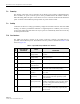
Table 2-4. Spectrum Transport Module User Interface, continued
REF
NO
USER INTERFACE
DESIGNATION
DEVICE
FUNCTIONAL
DESCRIPTION
18636-B
(3) ON/OFF
SWITCH
(4) AC POWER
CONNECTOR
(5) DC POWER
CONNECTOR
(1) PORT 1
CONNECTOR
(2) PORT 2
CONNECTOR
(6) SERVICE
CONNECTOR
(7-13) LED
INDICATORS
(14) ALARM
CONNECTOR
(15) ANTENNA
CONNECTOR