
User Manual


ADCP-75-159 • Issue 1 • August 2003 • Section 2: Description
Page 2-28
© 2003, ADC Telecommunications, Inc.
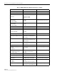
Optical receive input –7 dBm maximum
Optical connectors Industry standard SC Host, remote, and WDM
Optical - Host and Remote WDM
Passband
1310 nm ± 20 nm
1550 nm ± 20 nm
Forward path insertion loss
Host WDM
Remote WDM
0.7 dB
0.3 dB
Does not include connector loss
Reverse path insertion loss
Host WDM
Remote WDM
0.3 dB
0.7 dB
Does not include connector loss
Isolation > 30 dB minimum
Return loss (Reflectance) < –50 dB All input ports
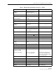
RF Forward Path - SMR 800 MHz
System bandwidth
15 MHz
Frequency range 851 to 866 MHz SMR band
Gain of forward path
(Host input to Remote antenna
port)
80.5 dB at band center, room
temperature, and 0 dB attenua-
tion setting
Includes power amplifier.
Gain flatness ± 1.5 dB across freq. range
1 dB variation across any 1.25
MHz channel
Gain variation ± 3 dB over temperature and
unit-to-unit
Propagation delay 6 µs maximum Excludes fiber delay
Configurable propagation delay
Range
Step size
Up to 63 µs
1 µs
Plus standard propagation delay
Spurious
In-band self generated
Dynamic range
–13 dBm at remote output
–65 dBc
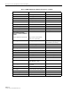
Transmit peak-to-average 10 dB
Intermodulation products –65 dBc
Nominal composite RF input
signal level
–40 dBm at 0 dB attenuation
–20 dBm at max. attenuation
An input signal level of –40 dBm
provides maximum output power
Configurable input level
Range
Step size
20 dB
1 ± 0.5 dB ±10% of step value
Composite RF output power 40.5 dBm (11 Watts) at remote
antenna port with –40 dBm input
20 Watts at power amplifier out-
put
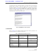
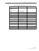
Table 2-6. SMR 20 Watt System Nominal Specifications, continued
PARAMETER SPECIFICATION REMARKS