
User Manual


ADCP-75-159 • Issue 1 • August 2003 • Section 3: Host Unit Installation
Page 3-9
© 2003, ADC Telecommunications, Inc.
2. Designate one of the patch cords as the forward path link and the other as the reverse
path link and attach an identification label or tag next to each connector.
3. Remove the dust caps from the HU optical ports and from the patch cord connectors that
will be connected to the HU.
4. Clean each patch cord connector (follow patch cord supplier’s recommendations).
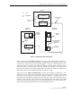
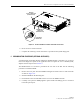
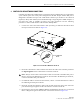
5. Insert the connector into the appropriate optical port as shown in Figure 3-7.
Figure 3-7. Fiber Optic Cable Connections To Host Unit
6. Route the patch cords from the HU to the fiber distribution panel.
7. At the fiber distribution panel, identify the OSP optical fiber terminations that correspond
to the forward and reverse path.
8. Remove the dust caps from the from the patch cord connectors.
9. Clean each patch cord connector (follow patch cord supplier’s recommendations) and then
mate the connector with the appropriate OSP optical fiber termination.
10. Store any excess patch cord slack at the fiber distribution panel.
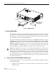
Note: To protect the optical receivers, insert a 10 dB attenuator in each optical path. After
the optical power has been measured, the attenuator may be resized or removed.
Note: The HU optical adapters are angled to the left. Therefore, patch cords should always
be routed to the HU from the left side of the rack. Routing patch cords to the HU from the
right side of the rack may exceed the bend radius limitations for the optical fiber.
18828-A
SC OPTICAL
CONNECTOR
PORT 1
FORWARD PATH
PORT 2
REVERSE PATH