
User Manual


ADCP-75-159 • Issue 1 • August 2003 • Section 3: Host Unit Installation
Page 3-8
© 2003, ADC Telecommunications, Inc.
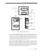
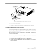
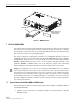
Figure 3-6. WDM Installation
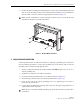
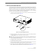
7 OPTICAL CONNECTIONS
The optical interface between the HU and the RU is supported by two optical ports. Each optical
port consists of an SC optical adapter which is mounted on the HU rear panel. Port 1 provides
the optical fiber connection for the forward path (downlink) signal. Port 2 provides the optical
fiber connection for the reverse path (uplink) signal.
The optical connections are dependent on whether or not a WDM host module (accessory) or
CWDM host module (accessory) is installed. If the installation does not include either a WDM or
CWDM module, proceed to Section 7.1 for the optical connections procedure. If the installation
includes a WDM module, proceed to Section 7.2 for the optical connections procedure. If the
installation includes a CWDM module, refer to the Digivance System Coarse Wavelength
Division Multiplexer User Manual (ADCP-75-142) for the optical connection procedure.
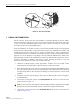
7.1 Optical Connections Without WDM or CWDM system
Use the following procedure to connect the optical fibers when a WDM or CWDM host module is
not installed with the HU:
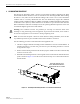
1. Obtain two patch cords that are of sufficient length to reach from the HU to the fiber
distribution panel.
Danger: This equipment uses a Class 1 Laser according to FDA/CDRH rules. Laser radiation
can seriously damage the retina of the eye. Do not look into the ends of any optical fiber. Do not
look directly into the optical transmitter of any unit or exposure to laser radiation may result.
An optical power meter should be used to verify active fibers. A protective cap or hood MUST
be immediately placed over any radiating transmitter or optical fiber connector to avoid the
potential of dangerous amounts of radiation exposure. This practice also prevents dirt particles
from entering the connector.
18827-A
REMOVE COVER PLATE
FOR WDM MODULE
INSTALLATION
WDM MODULE