
User Manual


ADCP-75-159 • Issue 1 • August 2003 • Section 3: Host Unit Installation
Page 3-6
© 2003, ADC Telecommunications, Inc.
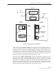
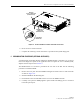
Figure 3-4. Chassis Ground Stud
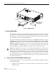
5 COAXIAL CABLE CONNECTIONS
The RF interface between the HU and the EBTS is supported through two N-type female
connectors mounted on the HU rear panel. One connector provides the coaxial cable connection
for the forward path (downlink) signal and the other connector provides the coaxial cable
connection for the reverse path (uplink) signal.
In most installations, it is usually necessary to insert some attenuation in the forward path link
between the HU and the EBTS. A signal level that is greater than –20 dBm will overdrive and
possibly damage the HU receiver. Refer to Section 4, Subsection 2.3, before completing the
forward path connection at the EBTS. If the Primary Interface Panel and Expansion Panel are
required, refer to the Digivance Long Range Coverage Solution SMR Interface Panels User
Manual (ADCP-75-143) for the installation procedures. The HU should be mounted as close as
possible to the EBTS to minimize cable losses. Use the following procedure to route and
connect the forward and reverse path coaxial cables to the HU:
1. Obtain the required lengths of high performance, flexible, low loss 50-ohm coaxial
communications cable (RG-400 or equivalent) for all coaxial connections.
2. Route the forward and reverse path coaxial cables between the HU and the EBTS interface
(per system design plan) and cut to the required length. Allow sufficient slack for dressing
and organizing cables at the HU and for installing an external attenuator in the forward
path link.
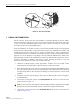
3. Terminate each cable with an N-type male connector following the connector supplier’s
recommendations.
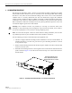
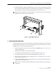
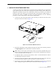
4. Connect the forward path cable to the FORWARD RF IN connector on the HU front
panel as shown in Figure 3-5.
5. Connect the reverse path cable to the REVERSE RF OUT connector on the HU front
panel (see Figure 3-5).
Note: Do not connect the forward path cable at the EBTS until the composite forward path
RF signal level is measured and the amount of attenuation required is determined.
17866-A