
User Manual


ADCP-75-159 • Issue 1 • August 2003 • Section 3: Host Unit Installation
Page 3-5
© 2003, ADC Telecommunications, Inc.
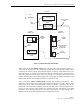
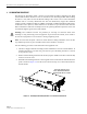
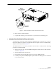
4. Position the HU in the designated mounting space in the rack (per system design plan) and
then secure the mounting brackets to the rack using the four machine screws provided (use
#12-24 or M6 x 10 screws, whichever is appropriate) as shown in Figure 3-3.
Figure 3-3. HU Rack Mount Installation
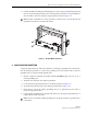
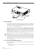
4 CHASSIS GROUND CONNECTION
A stud is provided on the rear side of the chassis for connecting a grounding wire to the chassis.
Use the following procedure to connect the grounding wire to the chassis and to route the
grounding wire to an approved earth ground source.
1. Obtain a length of #18 AWG (1.00 mm) insulated stranded copper wire for use as a
chassis grounding wire.
2. Terminate one end of the wire with a ring terminal.
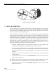
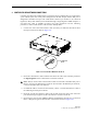
3. Locate the chassis ground stud at the rear of the HU as shown in Figure 3-4.
4. Attach the ring end of the wire to the chassis ground stud (see Figure 3-4).
5. Route the free end of the chassis grounding wire to an approved (per local code or
practice) earth ground source.
6. Cut the chassis grounding wire to length and connect it to the approved ground source as
required by local code or practice.
Note: Provide a minimum of 3 inches (76 mm) of clearance space on both the left and
right sides of the HU for air intake and exhaust.
Note: Be sure to maintain reliable grounding. Pay particular attention to ground source
connections.
17865-A