
User's Manual


ADCP-75-158 • Issue 1 • July 2003 • Section 1: Overview
Page 1-4
© 2003, ADC Telecommunications, Inc.
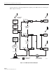
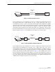
Figure 1-3. BTS/HU Interface With Conditioning Panel and Duplexing Panel
2.3 Handset Interface
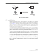
The RU interfaces with the handsets (cell phones) through an antenna. In the reverse path, the
RU receives RF signals from each handset. The RU digitizes the RF signals and then converts
them to digital optical signals for transport to the HU over the fiber optic link. In the forward
path, the RU receives digital optical signals from the HU. The RU converts the optical signals to
RF signals for transmission to the handsets. The RU is connected to an antenna (not provided)
which transmits and receives the handset RF signals.
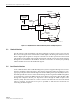
2.4 Local Service Interface
Local communications with an individual Digivance system is supported through a local service
interface capability as shown in Figure 4. The primary component of the local interface is a PC-
type laptop computer loaded with the Digivance Element Management System (EMS) software.
The EMS provides the various control and monitoring functions required for local management
of each Digivance system. The EMS computer can be directly connected to either the HU or RU
through the computer’s RS-232 port. Operation is done through the EMS Graphical User
Interface (GUI). The GUI consists of a series of screens from which the user selects the desired
option or function. An RS-232 service port is provided on both the HU and the RU for
connecting the EMS computer.
18515-A
RF
RF
RF
RF
RF
BASE
TRANSCEIVER
STATION
COAXIAL
CABLES
COAXIAL
CABLES
HOST UNIT
HOST UNIT
HOST UNIT
CONDITIONING
PANEL
DUPLEXING
PANEL