
User Manual

ADCP-75-158 • Preliminary Issue A • June 2003 • Section 2: Description
Page 2-18
© 2003, ADC Telecommunications, Inc.
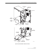
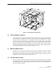
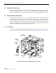
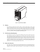
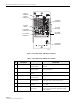
Figure 2-8. Spectrum Transport Module User Interface
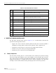
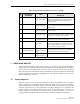
Table 2-4. Spectrum Transport Module User Interface
REF
NO
USER INTERFACE
DESIGNATION
DEVICE
FUNCTIONAL
DESCRIPTION
1 PORT 1 SC connector
(single-mode)
Input connection point for the forward path opti-
cal fiber.
2 PORT 2 SC connector
(single-mode)
Output connection point for the reverse path pri-
mary optical fiber.
3 I/0 On/Off rocker
switch
Provides AC power on/off control.
4 No designation 3-wire AC power
cord connector
Connection point for the AC power cord.
5 No designation 2- wire DC power
cord connector
Connection point for a back-up battery power
cord. (Not used with 20 Watt system)
6 SERVICE DB-9 connector
(female)
Connection point for the RS-232 service inter-
face cable.
7 AC POWER Multi-colored LED
(green/red)
Indicates if the STM is powered by the AC power
source (green) or the back-up battery system
(red). See Note.
18636-B
(3) ON/OFF
SWITCH
(4) AC POWER
CONNECTOR
(5) DC POWER
CONNECTOR
(1) PORT 1
CONNECTOR
(2) PORT 2
CONNECTOR
(6) SERVICE
CONNECTOR
(7-13) LED
INDICATORS
(14) ALARM
CONNECTOR
(15) ANTENNA
CONNECTOR