
User Manual

ADCP-75-150 • Preliminary Issue A • March 2003 • Section 4: Operation
Page 4-8
©
2003,
ADC
Telecommunications,
Inc.
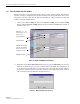
2. If
using
a
spectrum
analyzer,
proceed
to
step
3.
If
using
a
power
meter,
measure
the
composite
signal
power
from
the
BTS
and
then
proceed
to
step
5.
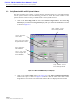
3. Measure
the
RF
level
of
a
single
carrier,
such
as
the
control
channel,
in
dBm.
Make
sure
the
resolution
bandwidth
of
the
spectrum
analyzer
is
30
kHz.
Maximum
power
in
any
channel
should
not
exceed
5W
(+37
dB).
4. Calculate
the
total
composite
signal
power
from
the
BTS
using
the
following
formula:
P
tot
=
P
c
+
10Log
N
–
(see
Note)
Where,
P
tot
is
the
total
composite
power
in
dBm
P
c
is
the
power
per
carrier
in
dBm
as
measured
in
step
3,
and
N
is
the
total
number
of
channels.
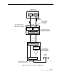
5. Determine
the
total
cable
loss
that
is
imposed
by
the
forward
path
coaxial
cable
that
links
the
BTS
to
the
HU
and
also
any
insertion
loss
imposed
by
splitters
or
combiners.
6. Subtract
the
total
cable
loss
and
any
insertion
losses
from
the
total
composite
power
calculated
in
step
4.
7. Subtract
–25
(midpoint
of
the
required
range)
from
the
value
determined
in
step
6.
The
difference
(which
should
be
positive)
equals
the
value
of
the
external
attenuator
that
is
required
to
reduce
the
forward
path
signal
level
to
fall
within
the
required
range.
The
following
formula
outlines
the
required
calculations
for
steps
6
and
7:
P
tot
–
(Cable
and
insertion
loss)
–
(–25)
=
Va l u e
of
external
attenuator
required
8. Select
an
attenuator
that
is
as
close
to
the
value
calculated
in
step
7
as
possible.
Select
a
value
that
will
adjust
the
signal
level
of
the
composite
input
signal
to
fall
within
the
specified
range.
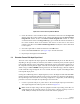
9. Install
the
external
attenuator
in
the
coaxial
cable
that
is
connected
to
the
FORWARD
RF
IN
port
at
the
HU.
10. Subtract
the
value
of
the
external
attenuator
used
in
step
9
from
the
total
composite
signal
power
(P
tot
)
and
record
the
result.
This
value
will
be
required
when
setting
the
attenuation
of
the
HU’s
internal
forward
attenuator.
Note:
If
calculating
the
composite
power
for
a
CDMA
system,
reduce
the
initial
result
by
16.23
dBm
Note:
If
the
input
signal
level
is
already
within
the
required
range
of
–10
to
–40
dBm,
then
no
external
attenuator
is
required.
Caution:
The
Host
Unit
can
be
damaged
if
it
is
overdriven
by
the
BTS.
Always
install
an
external
protective
attenuator
at
the
Host
Unit
FORWARD
RF
IN
port
if
the
forward
path
composite
input
signal
level
is
greater
than
–10
dBm.