
User Manual


ADCP-75-150 • Preliminary Issue A • March 2003 • Section 2: Description
Page 2-14
©
2003,
ADC
Telecommunications,
Inc.
4.5 Antenna Cable Connections
The
antenna
cable
should
be
routed
to
the
indoor
mounting
shelf
for
connection
to
the
STM
module.
If
lightning
protection
is
required,
it
is
recommended
that
a
lightning
protection
device
be
installed
near
the
point
where
the
antenna
cable
enters
the
building
or
enclosure.
4.6 AC Power Wiring and Grounding
A
standard
three-conductor
AC
power
cord
is
provided
with
the
indoor
mounting
shelf
for
the
AC
power
connections.
The
receptacle
end
of
the
power
cable
connects
to
the
AC
connector
on
the
STM.
The
plug
end
of
the
power
cable
connects
to
a
standard
120
Vac
outlet.
If
AC
power
spikes
are
likely
to
occur,
a
surge
protector
should
be
installed
to
protect
the
equipment
from
damage.
A
grounding
stud
is
provided
on
the
left
side
of
the
mounting
shelf
for
connecting
a
separate
grounding
wire
directly
to
the
mounting
shelf
chassis.
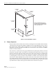
4.7 User Interface
The
RU
mounting
shelf
user
interface
consists
primarily
of
the
mounting
slots
and
AC
and
DC
power
cables.
The
user
interface
points
are
indicated
in
Figure 2-6
and
described
in
Table 2-3.
Figure 2-6. Remote Unit Indoor Mounting Shelf User Interface
18642-A
(1) STM MOUNTING
SLOT
(2) LPA MOUNTING
SLOT
(4) AC POWER
CABLE
(5) WDM MOUNTING
SLOT
(6) CWDM MOUNTING
SLOT
(7) CWDM DC
POWER CABLE
(3) GROUNDING
STUD