
User Manual


ADCP-75-150 • Preliminary Issue A • March 2003 • Section 2: Description
Page 2-13
©
2003,
ADC
Telecommunications,
Inc.
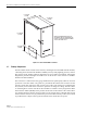
Figure 2-5. Remote Unit Indoor Mounting Shelf
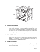
4.2 STM and LPA Module Installation
Two
mounting
slots
are
provided
within
the
indoor
mounting
shelf
for
installing
the
STM
and
LPA
modules.
The
mounting
slots
include
tracks
that
guide
each
module
into
the
installed
position.
Separate
mounting
slots
are
provided
for
STM
and
LPA
modules.
Two
D-sub
connectors
(one
male,
one
female)
are
located
at
the
rear
of
each
mounting
slot.
Each
mounting
slot
connector
mates
with
a
corresponding
D-sub
connector
located
on
the
rear
side
of
each
module.
A
wiring
harness
links
the
mounting
slot
connectors
together.
The
connectors
and
the
attached
wiring
harness
provide
the
electrical
interface
between
the
STM
and
LPA
modules.
The
modules
are
held
in
the
installed
position
with
captive
screws.
4.3 WDM and CWDM Installation
Mounting
slots
are
provided
in
the
indoor
mounting
shelf
for
installing
a
WDM
or
CWDM
module
(accessory
items).
Each
module
is
equipped
with
push-pull
type
fasteners
for
securing
the
module
to
the
mounting
slot.
A
power
cable
is
included
with
the
mounting
shelf
for
supplying
DC
power
when
a
CWDM
module
is
installed.
4.4 Fiber Optic Cable Installation
Fiber
optic
cables
and
patch
cords
should
be
routed
to
the
indoor
mounting
shelf
using
existing
fiber
management
systems.
All
fiber
optic
connections
are
made
directly
with
the
STM,
WDM,
or
CWDM
modules.
It
is
recommended
that
some
provision
be
made
at
the
mounting
shelf
for
storing
excess
patch
cord
slack.
18565-A
14.15 INCHES
(359 MM)
15.6 INCHES
(396 MM)
17.39 INCHES
(442 MM)