
User Manual


ADCP-75-150 • Preliminary Issue A • March 2003 • Section 2: Description
Page 2-10
©
2003,
ADC
Telecommunications,
Inc.
3.6 Antenna Cable Connection
An
N-type
female
connector
is
provided
on
the
exterior
bottom
side
of
the
RU
cabinet
for
connecting
the
primary
antenna
coaxial
cable.
The
exterior
connector
is
on
the
surge
side
of
a
lightning
protector
that
is
mounted
on
the
interior
bottom
side
of
the
enclosure.
On
the
inside
of
the
enclosure,
a
second
N-type
female
connector
is
provided
on
the
protected
side
of
the
lightning
protector.
A
coaxial
jumper
cable
(included
with
the
enclosure)
is
used
for
connecting
the
protected
side
N-type
connector
to
the
ANTENNA
port
on
the
STM.
3.7 AC Power Wiring and Grounding
The
RU
outdoor
cabinet
is
equipped
with
a
3-foot
long
stub
cable
for
the
AC
power
connections.
The
AC
power
cable
provides
three
wire
leads
(Load,
Neutral,
and
Ground)
that
must
be
connected
to
a
120
or
240
Vac
power
source.
The
AC
power
cable
exits
the
cabinet
though
a
3/4-inch
NPT
threaded
hole
located
on
the
bottom
of
the
cabinet.
The
threaded
hole
accepts
a
standard
3/4-inch
AC
conduit
fitting.
A
3/4-inch
to
1/2-inch
reducer
is
also
included
if
1/2-inch
conduit
is
preferred
over
3/4-inch
conduit.
From
the
exit
point
in
the
bottom
of
the
cabinet,
the
AC
power
cable
must
be
routed
through
conduit
to
an
external
AC
junction
box
(not
provided)
where
it
can
be
connected
to
the
AC
power
wiring.
The
junction
box
should
be
located
within
two
feet
of
the
cabinet
and
should
be
equipped
with
a
120
Vac
outlet
for
powering
test
equipment
and/or
power
tools.
If
AC
power
spikes
are
likely
to
occur,
the
junction
box
should
also
include
a
surge
protector
to
protect
the
equipment
from
damage.
Three
wire
nuts
are
included
with
the
cabinet
for
completing
the
AC
power
wiring
connections.
The
junction
box
wiring
should
be
connected
to
the
AC
power
source
through
a
20
Amp
breaker
box
(not
provided).
All
AC
power
wiring
should
be
run
within
conduit.
A
grounding
lug
is
provided
on
the
underside
of
the
enclosure
for
connecting
a
separate
grounding
wire
directly
to
the
cabinet.
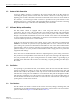
3.8 Ventilation
Vent
openings
are
provided
in
the
door,
on
the
bottom,
and
on
the
rear
side
of
the
RU
cabinet
to
permit
air
exchange
for
cooling.
Air
enters
the
cabinet
through
the
openings
in
the
door
and
bottom.
Filters
remove
dirt
particles
so
that
only
clean
air
enters
the
enclosure.
Both
the
STM
and
LPA
have
cooling
fans.
The
STM
has
a
rear
mounted
fan
that
pulls
air
through
the
module
and
exhausts
it
toward
the
rear
of
the
enclosure.
The
LPA
has
a
fan
on
the
front
that
draws
air
into
the
module
and
exhausts
it
toward
the
rear
of
the
enclosure.
The
heated
air
exits
through
an
opening
in
the
rear
side
of
the
enclosure.
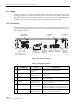
3.9 User Interface
The
RU
cabinet
user
interface
consists
of
the
various
connectors,
fittings,
mounting
slots,
and
switches
that
are
provided
on
both
the
interior
and
exterior
of
the
enclosure.
The
user
interface
points
are
indicated
in
Figure 2-4
and
described
in
Table 2-2.