
User Manual


ADCP-75-150 • Preliminary Issue A • March 2003 • Section 2: Description
Page 2-9
©
2003,
ADC
Telecommunications,
Inc.
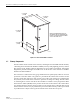
3.2 Mounting
The
RU
cabinet
may
be
mounted
on
a
flat
vertical
surface
(such
as
the
side
of
building)
on
a
utility
pole,
or
on
a
pedestal.
A
special
mounting
bracket
is
provided
with
each
enclosure.
Installation
consists
of
securing
the
bracket
to
the
mounting
surface
and
then
hanging
the
enclosure
from
the
bracket.
The
mounting
bracket
may
be
attached
to
a
variety
of
surfaces
such
as
wood,
concrete,
or
masonry.
Various
fasteners
including
hex-head
capscrews,
tee-nuts,
and
concrete
anchors
are
provided.
A
pedestal-mounting
kit
(accessory
item)
is
available
for
mounting
the
cabinet
on
a
flat
horizontal
surface.
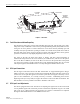
3.3 STM and LPA Module Installation
Two
mounting
slots
are
provided
within
the
RU
cabinet
for
installing
the
STM
and
LPA
modules.
The
mounting
slots
include
tracks
that
guide
each
module
into
the
installed
position.
Separate
mounting
slots
are
provided
for
STM
and
LPA
modules.
Two
D-sub
connectors
(one
male,
one
female)
are
located
at
the
rear
of
each
mounting
slot.
Each
mounting
slot
connector
mates
with
a
corresponding
D-sub
connector
located
on
the
rear
side
of
each
module.
A
wiring
harness
links
the
mounting
slot
connectors
together.
The
connectors
and
the
attached
wiring
harness
provide
the
electrical
interface
between
the
STM
and
LPA
modules.
The
modules
are
held
in
the
installed
position
with
captive
screws.
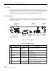
3.4 WDM and CWDM Intallation
A
mounting
slot
is
provided
within
the
RU
cabinet
for
installing
a
WDM
or
CWDM
module
(accessory
items).
Each
module
is
equipped
with
push-pull
type
fasteners
for
securing
the
module
to
the
mounting
slot.
A
power
cable
is
included
with
the
cabinet
for
providing
power
when
a
CWDM
module
is
installed.
A
fiber
storage
spool
is
provided
for
storing
excess
pigtail
and/or
patch
cord
slack.
3.5 Fiber Optic Cable Entry
A
plastic
cord
connector
is
provided
in
the
exterior
bottom
side
of
the
RU
cabinet
for
routing
a
fiber
optic
cable
into
the
enclosure.
The
cord
connector
provides
cable
strain
relief
and
a
watertight
seal
at
the
fiber
optic
cable
entry
point.
As
the
connector
nut
is
tightened,
a
soft
neoprene
bushing
compresses
to
tightly
grip
the
cable
without
applying
excessive
force
to
the
fibers.
The
cord
connector
can
accommodate
cables
that
range
from
0.375
to
0.875
inches
(10
to
23
mm)
in
diameter.
A
spool
is
provided
directly
above
the
fiber
optic
cable
entry
hole
for
storing
excess
pigtail
slack.
In
a
typical
installation,
the
connectorized
end
of
a
mulit-fiber
outside
plant
cable
is
routed
into
the
enclosure
through
the
cord
connector
and
the
individual
fibers
are
broken
out
into
pigtails.
The
pigtails
are
connected
to
the
optical
ports
on
the
STM
and
the
excess
pigtail
slack
is
stored
on
the
fiber
storage
spool.
The
stub
end
of
the
cable
is
routed
to
an
external
splice
enclosure
(not
provided)
for
splicing
to
the
fiber
optic
cable.