
User Manual


ADCP-75-150 • Preliminary Issue A • March 2003 • Section 2: Description
Page 2-7
©
2003,
ADC
Telecommunications,
Inc.
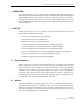
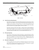
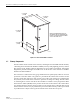
3 REMOTE UNIT OUTDOOR CABINET
The
RU
cabinet,
shown
in
Figure 2-3,
is
a
NEMA-3R
enclosure
(with
removable
dust
filters)
that
provides
the
following
basic
functions:
• Houses
the
various
electronic
modules
(STM
and
LPA)
and
accessories
(WDM
or
CWDM)
and
protects
them
from
the
weather.
• Provides
electrical
interface
connections
for
the
STM
and
LPA
modules.
• Provides
ventilation
openings
to
allow
for
entry
of
cool
air
and
the
escape
of
heated
air.
• Provides
a
point
for
connecting
the
antenna
cable,
fiber
optic
cable,
AC
power
wiring,
and
ground
cable.
• Provides
a
point
for
connecting
a
standard
AC
power
conduit
fitting.
• Provides
lightning
protection
• Provides
limited
storage
for
fiber
optic
pigtails
and
patch
cords.
• Provides
electrical
connections
for
the
CWDM
7REMOTE
UNIT Multi-colored
LED
(green/yellow/red)
Indicates
if
no
alarms
(green),
a
minor
alarm
(yellow),
or
a
major
alarm
(red)
is
reported
by
the
RU.
See
Note.
8 DRIVE Multi-colored
LED
(green/yellow/red)
Indicates
if
the
level
of
the
RF
input
signal
to
the
HU
is
normal
(green),
low
(yellow),
or
high
(red).
See
Note.
9PORT
1/PORT
2 Multi-colored
LED
(green/yellow/red)
Indicates
if
the
reverse
path
optical
signal
received
from
the
RU
is
normal
(green)
or
if
errors
are
detected
(red).
See
Note.
10 SERVICE DB-9
connector
(female)
Connection
point
for
the
RS-232
service
inter-
face
cable.
11 NET
IN RJ-45
jack
(female) Connection
point
for
CAN
interface
input
cable.
12 NET
OUT RJ-45
jack
(female) Connection
point
for
CAN
interface
output
cable.
13 ALARM
OUTPUT Screw-type
terminal
connector
(14–26
AWG)
Connection
point
for
an
external
alarm
system.
Includes
normally
open
(NO),
normally
closed
(NC),
and
common
(COM)
wiring
connections.
14 REVERSE
RF
OUT
N-type
female
RF
coaxial
connector
Output
connection
point
for
the
primary
reverse
path
RF
coaxial
cable.
15 FORWARD
RF
IN N-type
female
RF
coaxial
connector
Input
connection
point
for
the
forward
path
RF
coaxial
cable.
POWER
24–48
VDC
(Rear
side
-
not
shown)
Screw-type
terminal
strip
Connection
point
for
the
DC
power
wiring.
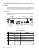
Note:
A
more
detailed
description
of
LED
operation
is
provided
in
Section
5.
Table 2-1. Host Unit User Interface, continued
REF
NO
USER INTERFACE
DESIGNATION
DEVICE
FUNCTIONAL
DESCRIPTION