
User Manual


ADCP-75-150 • Preliminary Issue A • March 2003 • Section 2: Description
Page 2-6
©
2003,
ADC
Telecommunications,
Inc.
2.11 Cooling
Continuous
airflow
for
cooling
is
provided
by
dual
fans
mounted
on
the
right
side
of
the
HU
housing.
A
minimum
of
3
inches
(76
mm)
of
clearance
space
must
be
provided
on
both
the
left
and
right
sides
of
the
HU
for
air
intake
and
exhaust.
An
alarm
is
provided
if
a
high
temperature
condition
(>50º
C/122º
F)
occurs.
The
fans
may
be
field-replaced
if
either
fan
fails.
2.12 User Interface
The
HU
user
interface
consists
of
the
various
connectors,
switches,
terminals,
and
LEDs
that
are
provided
on
the
HU
front
and
rear
panels.
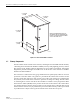
The
user
interface
points
are
indicated
in
Figure 2-2
and
described
in
Table 2-1.
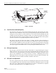
Figure 2-2. Host Unit User Interface
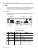
Table 2-1. Host Unit User Interface
REF
NO
USER INTERFACE
DESIGNATION
DEVICE
FUNCTIONAL
DESCRIPTION
1 I/0 On/Off
rocker
switch
Provides
DC
power
on/off
control.
2PORT
1SC
connector
(single-mode)
Output
connection
point
for
the
forward
path
optical
fiber.
3PORT
2SC
connector
(single-mode)
Input
connection
point
for
the
reverse
path
pri-
mary
optical
fiber.
4 POWER Multi-colored
LED
(green/yellow)
Indicates
if
the
HU
is
powered
(green)
or
unpow-
ered
(off).
See
Note.
5 STANDBY Multi-colored
LED
(green/yellow/red)
Indicates
if
the
system
is
in
the
Normal
(off),
Standby
(blinking
green),
Test
(blinking
red),
or
Program
Load
(blinking
yellow)
state.
See
Note.
6 HOST
UNIT Multi-colored
LED
(green/yellow/red)
Indicates
if
the
HU
is
normal
(green),
overheated
(yellow),
or
faulty
(red).
See
Note.
(1) DC POWER
ON/OFF SWITCH
NOTE: SHOWN WITHOUT
CABLE MANAGEMENT TRAY
(2)
PORT 1
(3)
PORT 2
(REFERENCE
ITEMS 4 - 9)
LED INDICATORS
(10) SERVICE
INTERFACE
CONNECTOR
(11) NET IN
CONNECTOR
(12) NET OUT
CONNECTOR
(13) ALARM
OUTPUT
CONNECTOR
(14) REVERSE
RF OUT
(15) FORWARD
RF IN
18532-A