
User Manual


ADCP-75-150 • Preliminary Issue A • March 2003 • Section 2: Description
Page 2-5
©
2003,
ADC
Telecommunications,
Inc.
The
host
forward
path
attenuator
adjusts
the
level
of
the
input
RF
signal
to
the
HU.
Using
the
forward
path
attenuator,
an
input
signal
with
a
nominal
composite
signal
level
of
–10
dBm
to
–40
dBm
can
be
adjusted
to
produce
maximum
power
output.
Additional
external
attenuation
is
required
if
the
input
signal
level
is
greater
than
–10
dBm.
The
host
reverse
path
attenuator
adjusts
the
level
of
the
output
RF
signal
and
will
add
from
–1
dB
of
attenuation
(attenuator
set
to
31
dB)
to
30
dB
of
gain
(attenuator
set
to
0
dB)
to
the
output
signal
at
the
HU.
2.6 Propagation Delay
The
HU
forward,
reverse,
and
diversity
reverse
path
propagation
delays
may
be
adjusted
in
0.1
µsec
increments
within
a
range
of
0–63
µ s.
The
propagation
delay
is
software
controlled
and
may
be
adjusted
through
the
NOC/NEM
interface
or
the
DEMS
software
GUI.
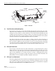
2.7 Optical Connection
Optical
connections
between
the
HU
and
the
RU
(STM)
are
supported
through
two
SC-type
optical
connector
ports.
One
port
is
used
for
connecting
the
forward
path
optical
signal
and
the
other
port
is
used
for
connecting
the
primary
reverse
path
optical
signal.
2.8 Controller Area Network Interface Connection
Controller
Area
Network
(CAN)
interface
connections
between
multiple
HUs
are
supported
by
a
pair
of
RJ-45
jacks.
One
of
the
jacks
is
designated
as
the
network
IN
port
and
the
other
jack
is
designated
as
the
network
OUT
port.
The
CAN
interface
allows
up
to
24
HUs
to
be
connected
together
(in
daisy-chain
fashion)
and
controlled
through
a
single
Digivance
DEMS
computer.
2.9 Service Interface Connection
The
service
interface
connection
between
the
HU
and
the
Digivance
DEMS
computer
is
supported
by
a
single
DB-9
female
connector.
The
service
connector
provides
an
RS-232
DTE
interface.
When
multiple
HUs
are
networked
together,
the
supporting
DEMS
computer
may
be
connected
to
the
service
connector
of
any
one
of
the
networked
HUs.
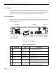
2.10 Powering
The
HU
is
powered
by
±
24
or
±
48
Vdc
power.
The
power
is
fed
to
the
HU
through
a
screw-
down
type
terminal
strip
located
on
the
rear
side
of
the
unit.
Power
to
the
HU
must
be
supplied
through
a
fuse
panel
such
as
the
20
position
PowerWorx
fuse
panel
(available
separately).
The
power
circuit
for
each
HU
must
be
protected
with
a
3
Amp
GMT
fuse.
An
On/Off
switch
is
provided
on
the
HU
front
panel.