
User Manual


ADCP-75-150 • Preliminary Issue A • March 2003 • Section 2: Description
Page 2-4
©
2003,
ADC
Telecommunications,
Inc.
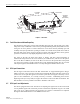
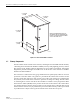
Figure 2-1. Host Unit
2.3 Fault Detection and Alarm Reporting
The
HU
detects
and
reports
various
faults
including
host
unit
fault,
optical
fault,
power
fault,
temperature
fault,
and
RF
fault.
Various
front
panel
Light
Emitting
Diode
(LED)
indicators
turn
from
green
to
red
or
yellow
if
a
fault
is
detected.
A
set
of
alarm
contacts
(normally
open
and
normally
closed)
are
provided
for
reporting
an
alarm
to
an
external
alarm
system
when
a
fault
is
detected.
Both
major
alarm
(system
operation
seriously
affected)
and
minor
alarm
(system
operation
not
affected
or
only
slightly
degraded)
contacts
are
provided.
The
status
of
the
HU,
the
alarm
state
(major
or
minor),
and
other
alarm
information
is
summarized
and
reported
over
the
service
interface,
the
CAN
interface,
and
also
over
the
optical
fiber
to
the
RU.
In
addition,
the
state
of
the
RU
is
received
over
the
optical
fiber
and
reported
over
the
service
interface
and
the
CAN
interface.
This
detailed
information
may
be
accessed
remotely
through
the
NOC/NEM
interface
or
locally
through
the
DEMS
software
GUI.
2.4 RF Signal Connections
The
RF
signal
connections
between
the
HU
and
the
BTS
are
supported
through
two
N-type
female
connectors.
One
connector
is
used
for
the
forward
path
RF
signal.
The
other
connector
is
used
for
the
reverse
path
RF
signal.
The
20
Watt
system
does
not
support
a
diversity
reverse
path.
In
most
installations,
it
is
usually
necessary
to
install
a
Conditioning
Panel
and/or
Duplexing
Panel
(accessory
items)
to
support
the
interface
between
the
HU
and
the
BTS.
The
HU
should
be
as
close
as
possible
to
the
BTS
to
minimize
cable
losses.
2.5 RF Signal Level Adjustments
The
HU
is
equipped
with
several
attenuators
for
adjusting
the
signal
levels
of
the
forward
and
reverse
path
RF
signals.
The
attenuators
provide
an
attenuation
adjustment
range
of
0
to
31
dB
and
can
be
set
in
1
dB
increments.
The
attenuators
are
software
controlled
and
are
adjusted
through
the
NOC/NEM
interface
or
the
DEMS
software
GUI.
17.2 INCHES
(437 mm)
3.5 INCHES
(89 mm)
11.4 INCHES
(290 mm)
15.3 INCHES
(389 mm)
FRONT PANEL
CABLE MANAGEMENT
TRAY
MOUNTING
BRACKET
(BOTH SIDES)
18531-A