
User Manual


ADCP-75-150 • Preliminary Issue A • March 2003 • Section 2: Description
Page 2-3
©
2003,
ADC
Telecommunications,
Inc.
1 INTRODUCTION
This
section
describes
the
basic
components
of
the
Digivance
800
MHz
20
Watt
system
including
the
Host
Unit
(HU),
the
Remote
Unit
(RU),
and
the
Digivance
Element
Management
System
(DEMS).
The
RU
is
an
assembly
that
consists
of
a
cabinet
(for
outdoor
applications)
or
mounting
shelf
(for
indoor
applications),
a
Spectrum
Transport
Module
(STM),
and
a
Linear
Power
Amplifier
(LPA)
module.
For
clarity,
the
various
components
that
comprise
the
RU
are
described
separately.
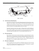
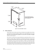
2 HOST UNIT
The
HU,
shown
in
Figure 2-1,
serves
as
the
BTS
servicing
unit
for
the
Digivance
system.
The
HU
provides
the
following
basic
functions:
• Provides
an
adjustable
RF
interface
with
the
BTS.
• Provides
a
fiber
optic
interface
with
the
RU.
• Digitizes
the
forward
path
composite
RF
signal.
•Converts
the
digitized
forward
path
RF
signal
to
a
digital
optical
signal.
•Converts
the
digitized
reverse
path
optical
signal
to
a
digitized
RF
signal.
•Converts
the
digitized
reverse
path
RF
signal
to
a
composite
RF
signal.
• Signals
alarm
information
to
an
external
alarm
system
through
relay
contact
closures
• Provides
an
RS-232
interface
for
connecting
the
DEMS
computer.
• Provides
a
CAN
interface
for
networking
multiple
HUs.
2.1 Primary Components
The
HU
consists
of
an
electronic
circuit
board
assembly
and
a
fan
assembly
that
are
mounted
within
a
powder-paint
coated
sheet
metal
enclosure.
The
enclosure
provides
a
mounting
point
for
the
circuit
board
and
fan
assemblies
and
controls
RF
emissions.
The
only
user-replaceable
component
is
the
fan
assembly.
The
HU
is
designed
for
use
within
a
non-condensing
indoor
environment
such
as
inside
a
wiring
closet
or
cabinet.
All
controls,
connectors,
and
indicators
(except
the
power
terminal
strip)
are
mounted
on
the
HU
front
panel
for
convenient
access.
Cable
management
functions
for
the
coaxial
cables
and
copper
wiring
are
provided
by
a
cable
management
tray
that
extends
outward
from
the
HU
front
panel.
2.2 Mounting
The
HU
is
intended
for
rack-mount
applications.
A
pair
of
reversible
mounting
brackets
is
provided
that
allow
the
HU
to
be
mounted
in
either
a
19-inch
or
23-inch
EIA
or
WECO
equipment
rack.
When
installed,
the
front
panel
of
the
HU
is
flush
with
the
front
of
the
rack.
The
cable
management
tray
extends
3.9
inches
(99
mm)
beyond
the
front
panel.
Fasteners
are
provided
for
securing
the
HU
to
the
equipment
rack.