
User Manual


ADCP-75-150 • Preliminary Issue A • March 2003 • Section 1: Overview
Page 1-6
©
2003,
ADC
Telecommunications,
Inc.
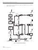
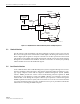
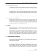
Figure 1-5. Remote NOC Interface
3 SYSTEM FUNCTIONS AND FEATURES
This
section
describes
various
system
level
functions
and
features
of
the
Digivance
System.
3.1 Fiber Optic Transport
In
a
typical
Digivance
20
Watt
system
with
a
single
HU
and
RU,
the
HU
is
connected
to
the
RU
over
a
pair
of
single-mode
optical
fibers.
One
fiber
is
used
to
transport
the
forward
path
optical
signal.
The
other
fiber
is
used
to
transport
the
reverse
path
optical
signal.
Because
the
optical
signal
is
digital,
the
input
and
output
RF
signal
levels
at
the
HU
or
the
RU
are
not
dependent
on
the
level
of
the
optical
signal
or
the
length
of
the
optical
fiber.
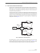
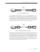
A
diagram
of
the
fiber
optic
transport
system
for
a
typical
Digivance
system
is
shown
in
Figure 1-6.
The
Digivance
20
Watt
system
does
not
support
reverse
path
diversity.
The
maximum
length
of
the
optical
fibers
is
dependent
on
the
loss
specifications
of
the
optical
fiber
and
the
losses
imposed
by
the
various
connectors
and
splices.
The
system
provides
an
optical
budget
of
25
dB
(typical)
when
used
with
9/125
single-mode
fiber.
DESKTOP COMPUTER WITH DEMS
(LOCAL AND REMOTE INTERFACE)
HOST UNIT
HOST UNIT
HOST UNIT
NETWORK
OPERATIONS
CENTER
(REMOTE
INTERFACE)
DATA
NETWORK
CONTROLLER
AREA
NETWORK
CONTROLLER
AREA
NETWORK
RS-232 ASCII
RS-232
18525-A
CD-ROM WITH DIGVANCE
ELEMENT MANAGEMENT
SYSTEM (DEMS) SOFTWARE
REMOTE
UNIT
REMOTE
UNIT
REMOTE
UNIT