
User Manual


ADCP-75-150 • Preliminary Issue A • March 2003 • Section 1: Overview
Page 1-1
©
2003,
ADC
Telecommunications,
Inc.
SECTION 1: OVERVIEW
1 INTRODUCTION. . . . . . . . . . . . . . . . . . . . . . . . . . . . . . . . . . . . . . . . . . . . . . . . . . . . . . . . . . . . . . . . . . . . . . . .1-1
2 800 MHZ 20 WATT SYSTEM OVERVIEW . . . . . . . . . . . . . . . . . . . . . . . . . . . . . . . . . . . . . . . . . . . . . . . . . . . . . . .1-1
2.1 Basic System Components . . . . . . . . . . . . . . . . . . . . . . . . . . . . . . . . . . . . . . . . . . . . . . . . . . . . . . . . . .1-1
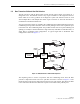
2.2 Base Transceiver Station to Host Unit Interface . . . . . . . . . . . . . . . . . . . . . . . . . . . . . . . . . . . . . . . . . . . .1-3
2.3 Handset Interface . . . . . . . . . . . . . . . . . . . . . . . . . . . . . . . . . . . . . . . . . . . . . . . . . . . . . . . . . . . . . . . .1-4
2.4 Local Service Interface. . . . . . . . . . . . . . . . . . . . . . . . . . . . . . . . . . . . . . . . . . . . . . . . . . . . . . . . . . . . .1-4
2.5 Remote NOC Interface . . . . . . . . . . . . . . . . . . . . . . . . . . . . . . . . . . . . . . . . . . . . . . . . . . . . . . . . . . . . .1-5
3 SYSTEM FUNCTIONS AND FEATURES . . . . . . . . . . . . . . . . . . . . . . . . . . . . . . . . . . . . . . . . . . . . . . . . . . . . . . . .1-6
3.1 Fiber Optic Transport . . . . . . . . . . . . . . . . . . . . . . . . . . . . . . . . . . . . . . . . . . . . . . . . . . . . . . . . . . . . . .1-6
3.2 Control and Monitoring Software . . . . . . . . . . . . . . . . . . . . . . . . . . . . . . . . . . . . . . . . . . . . . . . . . . . . . .1-9
3.3 Fault Detection and Alarm Reporting . . . . . . . . . . . . . . . . . . . . . . . . . . . . . . . . . . . . . . . . . . . . . . . . . . .1-9
3.4 Powering . . . . . . . . . . . . . . . . . . . . . . . . . . . . . . . . . . . . . . . . . . . . . . . . . . . . . . . . . . . . . . . . . . . . . .1-9
3.5 Equipment Mounting and Configuration . . . . . . . . . . . . . . . . . . . . . . . . . . . . . . . . . . . . . . . . . . . . . . . . .1-9
_________________________________________________________________________________________________________
1 INTRODUCTION
This
section
provides
basic
description,
application,
and
configuration
information
about
the
Digivance
800
MHz
20
Watt
System.
Throughout
this
publication,
all
items
referenced
as
“accessory
items”
are
not
furnished
with
the
basic
product
and
must
be
purchased
separately.
2 800 MHZ 20 WATT SYSTEM OVERVIEW
The
Digivance
800
MHz
20
Watt
System
is
an
RF
signal
transport
system
that
provides
long-
range
RF
coverage
in
areas
where
it
is
impractical
to
place
a
Base
Transceiver
Station
(BTS)
at
the
antenna
site.
High
real
estate
costs
and
community
restrictions
on
tower
and
equipment
locations
often
make
it
difficult
to
install
the
BTS
at
the
same
location
as
the
antenna.
The
Digivance
system
is
designed
to
overcome
equipment
placement
problems
by
allowing
base
stations
to
be
hubbed
at
a
central
location
while
placing
remote
antennas
at
optimum
locations
with
minimal
real
estate
requirements.
With
the
Digivance
system,
RF
signals
can
be
transported
to
one
or
more
remote
locations
to
expand
coverage
into
areas
not
receiving
service
or
to
extend
coverage
into
difficult
to
reach
areas
such
as
canyons,
tunnels,
or
underground
roadways.
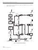
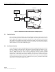
2.1 Basic System Components
The
basic
components
of
a
Digivance
20
Watt
System
and
their
functions
are
shown
in
Figure 1-1.
A
20
Watt
system
consists
of
the
Host
Unit
(HU)
and
the
Remote
Unit
(RU).
Both
an
indoor
and
an
outdoor
remote
unit
are
available.
Control
and
monitoring
functions
are
provided
by
the
Digivance
Element
Management
System
(DEMS),
a
PC-based
software
program.
In
addition,
various
accessory
items
are
available
separately
including
a
passive
Wavelength
Division
Multiplexer
(WDM),
an
active
Coarse
Wavelength
Division
Multiplexer
(CWDM)
system,
conditioning
and
duplexing
panels
(for
interfacing
the
HU
with
the
BTS),