
User Manual


ADCP-75-150 • Preliminary Issue A • March 2003 • Section 3: Host Unit Installation
Page 3-1
©
2003,
ADC
Telecommunications,
Inc.
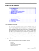
SECTION 3: HOST UNIT INSTALLATION
1 BEFORE STARTING INSTALLATION . . . . . . . . . . . . . . . . . . . . . . . . . . . . . . . . . . . . . . . . . . . . . . . . . . . . . . . . . .3-1
1.1 Tools and Materials . . . . . . . . . . . . . . . . . . . . . . . . . . . . . . . . . . . . . . . . . . . . . . . . . . . . . . . . . . . . . . .3-1
1.2 Unpacking and Inspection . . . . . . . . . . . . . . . . . . . . . . . . . . . . . . . . . . . . . . . . . . . . . . . . . . . . . . . . . . .3-2
2 OUTDOOR CABINET OSP FIBER CABLE INSTALLATION GUIDELINES . . . . . . . . . . . . . . . . . . . . . . . . . . . . . . . . . . . .3-2
3 WDM MOUNTING PROCEDURE (OPTIONAL ACCESSORY) . . . . . . . . . . . . . . . . . . . . . . . . . . . . . . . . . . . . . . . . . . .3-4
4 HU MOUNTING PROCEDURE . . . . . . . . . . . . . . . . . . . . . . . . . . . . . . . . . . . . . . . . . . . . . . . . . . . . . . . . . . . . . . .3-6
5 CHASSIS GROUND CONNECTION . . . . . . . . . . . . . . . . . . . . . . . . . . . . . . . . . . . . . . . . . . . . . . . . . . . . . . . . . . . .3-8
6 COAXIAL CABLE CONNECTIONS. . . . . . . . . . . . . . . . . . . . . . . . . . . . . . . . . . . . . . . . . . . . . . . . . . . . . . . . . . . . .3-8
7 OPTICAL CONNECTIONS. . . . . . . . . . . . . . . . . . . . . . . . . . . . . . . . . . . . . . . . . . . . . . . . . . . . . . . . . . . . . . . . . 3-10
7.1 Optical Connections Without WDM. . . . . . . . . . . . . . . . . . . . . . . . . . . . . . . . . . . . . . . . . . . . . . . . . . . . 3-10
7.2 Optical Connections With WDM . . . . . . . . . . . . . . . . . . . . . . . . . . . . . . . . . . . . . . . . . . . . . . . . . . . . . . 3-11
8 CONTROLLER AREA NETWORK CONNECTIONS . . . . . . . . . . . . . . . . . . . . . . . . . . . . . . . . . . . . . . . . . . . . . . . . . 3-13
9 SERVICE INTERFACE CONNECTION . . . . . . . . . . . . . . . . . . . . . . . . . . . . . . . . . . . . . . . . . . . . . . . . . . . . . . . . . 3-14
10 EXTERNAL ALARM SYSTEM CONNECTIONS . . . . . . . . . . . . . . . . . . . . . . . . . . . . . . . . . . . . . . . . . . . . . . . . . . . 3-15
11 DC POWER CONNECTIONS . . . . . . . . . . . . . . . . . . . . . . . . . . . . . . . . . . . . . . . . . . . . . . . . . . . . . . . . . . . . . . . 3-16
_________________________________________________________________________________________________________
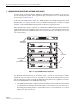
1 BEFORE STARTING INSTALLATION
This
section
provides
the
installation
procedures
for
the
HU,
the
WDM
mounting
shelf
(accessory),
and
the
WDM
module
(accessory).
Installation
of
the
RU
cabinet
or
mounting
shelf
and
the
RU
electronic
modules
may
proceed
separately
from
installation
of
the
HU.
The
mounting
procedures
for
the
outdoor
remote
cabinet
are
provided
in
the
20
Watt
Outdoor
Remote
Cabinet
Mounting
Instructions
(ADCP-75-147)
which
are
shipped
with
the
cabinet.
The
installation
procedures
for
the
STM
and
LPA
electronic
modules
are
provided
in
the
20
Watt
Indoor
Remote
Unit
Installation
Instructions
(ADCP-75-149)
and
the
20
Watt
Outdoor
Remote
Unit
Installation
Instructions
(ADCP-75-148)
which
are
shipped
respectively
with
the
outdoor
cabinet
and
indoor
mounting
shelf.
When
all
units
of
the
Digivance
system
have
been
installed,
refer
to
Section
4
of
this
manual
for
the
system
turn-up
and
test
procedures.
Before
beginning
the
installation,
review
the
system
design
plan
with
the
system
engineer.
Make
sure
each
equipment
installation
site
is
identified
and
located
and
all
cable
runs
are
mapped
out.
1.1 Tools and Materials
The
following
tools
are
required
to
complete
the
procedures
in
this
section:
•Box
cutter
• Pencil
or
scribe
•Medium
size
flat-bladed
screwdriver
• Phillips
screwdriver
(#2)
Content Page