
User Manual


ADCP-75-150 • Preliminary Issue A • March 2003 • Section 3: Host Unit Installation
Page 3-9
©
2003,
ADC
Telecommunications,
Inc.
possibly
damage
the
HU
receiver.
Refer
to
Section
4,
Subsection
2.3,
before
completing
the
forward
path
connection
between
the
BTU
and
HU.
If
the
Conditioning
Panel
or
Duplexing
Panel
is
required,
refer
to
the
Digivance
800
and
1900
MHz
Interface
Panels
User
Manual
(ADCP-75-147)
for
the
installation
procedures.
The
HU
should
be
mounted
as
close
as
possible
to
the
BTS
to
minimize
cable
losses.
Use
the
following
procedure
to
route
and
connect
the
forward
and
reverse
path
coaxial
cables
to
the
HU:
1. Obtain
the
required
lengths
of
high
performance,
flexible,
low
loss
50-ohm
coaxial
communications
cable
(RG-400
or
equivalent)
for
all
coaxial
connections.
2. Route
the
forward
and
reverse
path
coaxial
cables
between
the
HU
and
the
BTS
interface
(per
system
design
plan)
and
cut
to
the
required
length.
Allow
sufficient
slack
for
dressing
and
organizing
cables
at
the
HU
and
for
installing
an
external
attenuator
in
the
forward
path
link.
3. Terminate
each
cable
with
a
type
N
male
connector
following
the
connector
supplier’s
recommendations.
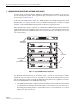
4. Connect
the
forward
path
cable
to
the
FORWARD
RF
IN
connector
on
the
HU
front
panel
as
shown
in
Figure 3-8.
Figure 3-8. Forward and Reverse Path Coaxial Cable Connections
5. Connect
the
reverse
path
cable
to
the
REVERSE
RF
OUT
connector
on
the
HU
front
panel
(see
Figure 3-8).
6. Dress
and
secure
cables
at
the
HU.
7. Complete
all
remaining
coaxial
connections
as
specified
in
the
system
design
plan.
Note:
Do
not
connect
the
forward
path
cable
at
the
BTS
until
the
composite
forward
path
RF
signal
level
is
measured
and
the
amount
of
attenuation
required
is
determined.
18655-A
TYPE-N MALE
CONNECTOR
FORWARD RF IN
CONNECTOR
(FORWARD PATH)
REVERSE
RF OUT CONNECTOR
(REVERSE PATH)