
User Manual


ADCP-75-150 • Preliminary Issue A • March 2003 • Section 3: Host Unit Installation
Page 3-8
©
2003,
ADC
Telecommunications,
Inc.
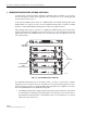
5 CHASSIS GROUND CONNECTION
A
stud
is
provided
on
the
rear
side
of
the
chassis
for
connecting
a
grounding
wire
to
the
chassis.
Use
the
following
procedure
to
connect
the
grounding
wire
to
the
chassis
and
to
route
the
grounding
wire
to
an
approved
earth
ground
source.
1. Obtain
a
length
of
#18
AWG
(1.00
mm)
insulated
stranded
copper
wire
for
use
as
a
chassis
grounding
wire.
2. Terminate
one
end
of
the
wire
with
a
ring
terminal.
3. Locate
the
chassis
ground
stud
at
the
rear
of
the
HU
as
shown
in
Figure 3-7.
Figure 3-7. Chassis Ground Stud
4. Attach
the
ring
end
of
the
wire
to
the
chassis
ground
stud
(see
Figure 3-7).
5. Route
the
free
end
of
the
chassis
grounding
wire
to
an
approved
(per
local
code
or
practice)
earth
ground
source.
6. Cut
the
chassis
grounding
wire
to
length
and
connect
it
to
the
approved
ground
source
as
required
by
local
code
or
practice.
6 COAXIAL CABLE CONNECTIONS
The
RF
interface
between
the
HU
and
the
BTS
is
supported
through
two
type
N
female
connectors
mounted
on
the
HU
front
panel.
One
connector
provides
the
coaxial
cable
connection
for
the
forward
path
(downlink)
signal
and
the
other
connector
provides
the
coaxial
cable
connection
for
the
reverse
path
(uplink)
signal.
In
most
installations,
it
is
usually
necessary
to
insert
some
attenuation
in
the
forward
path
link
between
the
HU
and
the
BTS.
A
signal
level
that
is
greater
than
–10
dBm
will
overdrive
and
Note:
Be
sure
to
maintain
reliable
grounding.
Pay
particular
attention
to
ground
source
connections.
16169-A