
User Manual


ADCP-75-136 • Issue 1 • November 2002
Page 4
©
2002,
ADC
Telecommunications,
Inc.
2 DIGTAL UNIT DESCRIPTION
This
section
provides
a
description
of
the
functions
and
features
provided
by
the
units
that
comprise
the
ICS
system,
a
listing
of
terms
used
and
their
definition,
and
a
table
of
specifications.
2.1 Digital Host Unit Description
The
DHU,
shown
in
Figure
2,
serves
as
the
BTS
servicing
unit
for
the
Digivance
ICS.
The
DHU
provides
the
following
basic
functions:
• RF
inputs
and
outputs
• Optical
interface
to
the
DRU’s
or
DEU’s
• Digitizing
of
the
cellular
forward
path
RF
signal
• Distribution
of
the
digitized
forward
path
RF
signals
into
six
digitized
optical
signals
• Conversion
of
up
to
six
reverse
path
digitized
optical
signals
to
six
digitized
RF
signals
• Combining
of
the
six
digitized
RF
signals
into
a
single
composite
digitized
RF
signal
• Conversion
of
the
combined
digitized
RF
signal
to
a
composite
RF
signal
• DC
power
for
powering
the
DRU’s
• Relay
contact
closures
to
provide
alarm
information
to
an
external
alarm
system
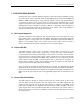
17.2 INCHES
(437 mm)
3.5 INCHES
(89 mm)
11.4 INCHES
(290 mm)
15.3 INCHES
(389 mm)
FRONT PANEL
CABLE MANAGEMENT
TRAY
MOUNTING
BRACKET
(BOTH SIDES)
17267-A
Figure 2. Digital Host Unit
2.1.1 Primary Components
The
DHU
consists
of
two
electronic
circuit
board
assemblies,
a
power
supply
assembly,
and
a
fan
assembly
that
are
mounted
within
a
powder-coated
sheet
metal
enclosure.
The
metal
enclosure
provides
a
mounting
point
for
the
electronic
assemblies,
serves
as
a
heat
sink,
and
controls
RF
emissions.
Except
for
the
fan
units
and
optical
transceivers,
the
DHU
components
are
not
field
replaceable.
The
DHU
is
designed
for
use
within
a
non-condensing
indoor
environment
such
as
inside
a
wiring
closet
or
cabinet.
All
controls,
connectors,
and
indicators
are
mounted
on
the
DHU
front
panel
for
convenient
access.
Cable
management
functions
for
the
power
and
fiber
optic
cables
are
provided
by
a
cable
management
tray
that
extends
outward
from
the
DHU
front
panel.