
User Manual

ADCP-75-136 • Issue 1 • November 2002
Page 12
©
2002,
ADC
Telecommunications,
Inc.
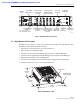
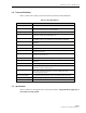
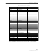
Table 3. Digital Expansion Unit User Interface
REF
No.
USER INTERFACE
DESIGNATION
DEVICE
FUNCTIONAL
DESCRIPTION
1
Grounding
stud
Used
for
connecting
a
grounding
cable
to
the
DEU
chassis.
2
POWER
3-wire
AC
power
cord
connector
Used
for
connecting
the
AC
power
cord.
3
I/O
I/O
rocker
switch/
circuit
breaker
Provides
AC
power
On/Off
control
and
AC
power
over
current
protection.
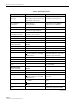
4
OK/NOK
(Ports
1–6)
Multi-colored
LED
(Red/Green/Yellow)
Indicates
if
the
DRU
or
remote
DEU
connected
to
the
optical
port
is
normal
or
faulty
or
if
the
reverse
path
optical
input
from
the
DRU
or
remote
DEU
is
normal
or
lost.
(see
Note)
5
ON/OFF
(Ports
1–6)
I/O
rocker
switch
Enables
or
disables
corresponding
electrical
and
optical
ports.
6
DC
PWR
(Ports
1–6)
RJ-45
jack
(female)
Used
for
connecting
a
DRU
cat
3
or
5
power
cable
to
the
designated
DC
power
jack.
7
FIBER
(Ports
1–6)
LC-type
optical
transceiver
Used
for
connecting
each
DRU
or
remote
DEU
forward
path
and
reverse
path
optical
fiber
to
the
designated
optical
port.
8
HOST
PORT
LC-type
optical
transceiver
Used
for
connecting
the
DHU
or
supporting
DEU
forward
path
and
reverse
path
optical
fiber.
9
UNIT
Multi-colored
LED
(Red/Green/Yellow)
Indicates
if
the
DEU
is
normal
or
faulty.
(see
Note)
10
HOST
PORT
Multi-colored
LED
(Red/Green/Yellow)
Indicates
if
the
forward
path
optical
input
from
the
DHU
or
supporting
DEU
is
normal
or
lost.
(see
Note)
Note:
A
more
detailed
description
of
LED
operation
is
provided
in
Section
5.
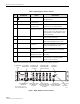
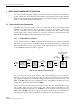
17266-A
(3) AC POWER
ON/OFF SWITCH
(1) GROUNDING
STUD
(4) OPTICAL PORT
LED INDICATOR
(6 PLACES)
(5) OPT/ELEC PORT
ENABLE/DISABLE
SWITCH (6 PLACES)
(9) UNIT LED
INDICATOR
(2) AC POWER CORD
CONNECTOR
(6) ELECTRICAL PORT
DC POWER JACK
(6 PLACES)
(7) OPTICAL PORT
OPTICAL TRANSCEIVER
TX-LEFT - RX-RIGHT
(6 PLACES)
(10) HOST PORT
LED
INDICATOR
(8) HOST PORT
OPTICAL TRANSCEIVER
TX-LEFT - RX-RIGHT
NOTE: SHOWN WITHOUT
CABLE MANAGEMENT TRAY
Figure 7. Digital Expansion Unit User Interface