
User Manual

ADCP-75-136 • Issue 1 • November 2002
Page 11
©
2002,
ADC
Telecommunications,
Inc.
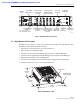
mounted
in
either
a
19-inch
or
23-inch
EIA
or
WECO
equipment
rack.
When
rack-mounted,
the
front
panel
of
the
DEU
is
flush
with
the
front
of
the
rack
and
the
cable
management
tray
extends
3.9
inches
(99
mm)
beyond
the
front
panel.
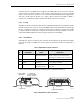
For
wall-mount
applications,
a
pair
of
holes
is
provided
in
the
cable
management
tray
which
allow
the
DEU
to
be
mounted
on
any
flat
vertical
surface.
The
DEU
should
be
oriented
with
the
front
panel
facing
upward
when
wall-mounted.
Fasteners
are
provided
for
rack-mount
applications.
2.3.3 Fault Detection
The
DEU
detects
internal
circuitry
faults
or
loss
of
system
inputs.
Various
front
panel
Light
Emitting
Diode
(LED)
indicators
turn
from
green
to
red
or
yellow
when
a
fault
is
detected
or
when
an
optical
input
is
lost.
The
DEU
transports
the
fault
information
to
the
DHU
or
supporting
DEU
over
the
reverse
path
optical
fiber.
A
corresponding
port
LED
at
the
DHU
or
DEU
turns
from
green
to
red
when
the
DEU
reports
a
fault.
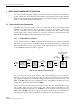
2.3.4 Optical and Electrical Connections
The
optical
and
electrical
connections
with
the
DRU’s
and
DEU’s
are
supported
by
six
optical
and
six
electrical
ports.
Each
optical
and
electrical
port
includes
a
status
LED,
a
small
form
factor
LC
type
optical
transceiver,
an
RJ-45
DC
power
jack,
and
a
port
enable/disable
switch.
Each
transceiver
is
color-coded
to
identify
whether
it
supports
single-mode
(blue)
or
multi-mode
(black/beige)
fiber.
An
optical
port
may
be
connected
to
a
DRU,
a
DEU,
or
not
used.
An
electrical
port
may
be
connected
to
a
DRU
or
not
used.
Unused
ports
are
disabled
via
the
corresponding
port
enable/disable
switch.
When
disabled,
the
port
LED
is
off,
the
alarm
reporting
function
is
disabled,
the
laser
is
off,
and
the
DC
power
is
off.
Enabling
the
enable/disable
switch
activates
all
functions.
The
DEU
also
provides
one
optical
port
(designated
as
the
host
port
)
for
the
optical
interface
with
the
DHU
or
a
supporting
DEU.
The
modular
optical
transceivers
are
available
separately
as
accessory
items
and
are
field
replaceable.
2.3.5 Powering
The
DEU
is
powered
by
120–240
Vac
(50–60
Hz)
power
which
is
supplied
though
a
standard
three-conductor
AC
power
cord.
The
power
cord
is
provided
with
the
DEU
and
is
98
inches
(2.5
meters)
long.
A
resetable
circuit
breaker/On-Off
switch
is
provided
at
the
unit
front
panel.
The
switch
applies
power
to
the
DEU
internal
power
supply.
2.3.6 Cooling
Continuous
air
flow
for
cooling
is
provided
by
dual
fans
mounted
on
the
right
side
of
the
sheet
metal
housing.
A
minimum
of
3
inches
(76
mm)
of
clearance
space
must
be
provided
on
both
the
left
and
right
sides
of
the
DEU
for
air
intake
and
exhaust.
An
alarm
is
provided
that
indicates
if
a
high
temperature
condition
(>50º
C/122º
F)
occurs.
The
fans
may
be
field-
replaced
if
either
unit
fails.
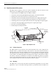
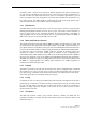
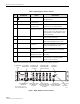
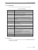
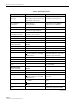
2.3.7 User Interface
The
DEU
user
interface
consists
of
the
various
connectors,
switches,
and
LEDs
that
are
provided
on
the
DEU
front
panel.
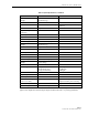
The
DEU
user
interface
points
are
described
in
Table
3
and
indicated
in
Figure
7.