
User Manual

ADCP-75-136 • Issue 1 • November 2002
Page 8
©
2002,
ADC
Telecommunications,
Inc.
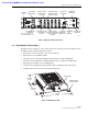
2.2.1 Primary Components
The
DRU
consists
of
an
electronic
circuit
board
assembly
that
is
mounted
within
a
powder-
coated
sheet
metal
enclosure.
The
metal
enclosure
provides
a
mounting
point
for
the
electronic
assembly,
serves
as
a
heat
sink,
and
controls
RF
emissions.
Except
for
the
optical
transceiver,
the
DRU
components
are
not
field
replaceable.
The
DRU
is
designed
for
use
within
a
non-
condensing
indoor
environment
such
as
inside
a
building.
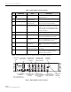
All
controls,
connectors,
and
indicators
(except
the
SMA
antenna
connector)
are
mounted
on
the
DRU
front
panel
for
convenient
access.
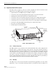
2.2.2 Mounting
The
DRU
is
equipped
with
four
integral
mounting
feet
that
allow
it
to
be
mounted
on
any
flat
horizontal
or
vertical
surface.
A
typical
location
for
mounting
the
DRU
would
be
on
a
ceiling
or
a
wall.
The
DRU
may
also
be
installed
in
spaces
used
for
environmental
air
such
as
the
space
over
a
suspended
ceiling
or
beneath
a
raised
floor.
Slots
are
provided
in
the
mounting
feet
for
securing
the
DRU
to
the
mounting
surface.
2.2.3 Fault Detection
The
DRU
detects
internal
circuitry
faults
or
loss
of
system
inputs.
A
front
panel
LED
indicator
turns
from
green
to
red
when
a
fault
condition
is
detected
or
when
the
optical
input
is
lost.
The
DRU
sends
the
fault
information
to
the
DHU
or
DEU
over
the
reverse
path
optical
fiber.
A
corresponding
port
LED
at
the
DHU
or
DEU
turns
from
green
to
red
when
the
DRU
reports
a
fault.
2.2.4 Antenna Connection
The
RF
signal
interface
between
the
DRU
and
the
cellular
users
is
provided
through
an
external
antenna.
An
SMA
connector
is
provided
for
connecting
the
DRU
to
the
antenna.
The
antenna
must
be
ordered
separately.
Several
types
of
antennas
with
various
RF
propagations
are
available.
Non-ADC
antennas
may
also
be
used
with
the
DRU
to
meet
various
application
requirements.
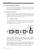
2.2.5 Optical Port
The
DRU
is
equipped
with
a
small
form
factor
LC-type
optical
transceiver
for
connecting
the
optical
fibers.
Each
transceiver
is
color-coded
to
identify
whether
it
supports
single-mode
(blue)
or
multi-mode
(black/beige)
fiber.
Depending
on
the
application
requirements,
the
optical
port
may
be
connected
to
either
a
DHU
or
a
DEU.
The
modular
optical
transceiver
is
available
separately
as
an
accessory
item
and
is
field
replaceable.
2.2.6 Powering
The
DRU
is
equipped
with
a
female
RJ-45
jack
that
provides
a
connection
point
for
the
DC
power
cable.
The
DRU
is
powered
by
34–48
Vdc
power
which
is
supplied
through
the
RJ-45