
User Manual

ADCP-75-136 • Issue 1 • November 2002
Page 16
©
2002,
ADC
Telecommunications,
Inc.
3 INSTALLATION PLANNING AND SYSTEM DESIGN
This
section
provides
installation
planning
information
and
basic
system
design
recommendations
for
RF
engineers
that
will
be
designing
and
installing
an
in-building
coverage
solution
using
the
Digivance
ICS.
System
design
and
planning
services
are
available
from
ADC
if
required.
Refer
to
Section
7
of
this
manual
for
additional
information.
3.1 Base Station Interface Requirements
The
DHU
may
be
interfaced
either
locally
or
remotely
with
the
BTS.
As
referenced
in
this
publication,
the
BTS
could
be
either
a
microcell
or
a
cell
site
base
station.
With
a
local
interface,
a
hard-wire
connection
is
provided
between
the
DHU
and
the
BTS
(microcell)
using
coaxial
cables.
With
a
remote
interface,
an
over-the-air
connection
is
provided
between
the
DHU
and
the
BTS
(cell
site
base
station)
using
a
donor
antenna.
3.1.1 Local BTS (Microcell) Interface
A
local
interface
between
the
DHU
and
the
BTS
(microcell)
over
coax
requires
specific
RF
input
and
output
signal
levels
at
the
DHU
and
BTS.
The
correct
levels
must
be
provided
at
the
BTS
and
DHU
interface
using
a
local
interface
device
(ancillary
product).
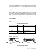
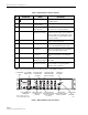
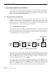
A
block
diagram
of
a
typical
local
BTS
interface
is
shown
in
Figure
8.
LOCAL
INTERFACE
DEVICE
(ANCILLARY
PRODUCTS)
FORWARD
(DOWNLINK)
REVERSE
(UPLINK)
+13 dBm
(COMPOSITE MAX)
-40 dBm
(COMPOSITE
MAX)
-20 dBm
(COMPOSITE MAX)
-30 dBm
(COMPOSITE MAX)
18110-A
DIGITAL
HOST
UNIT
OPTICAL LINK
OPTICAL LINK
DIGITAL
REMOTE
UNIT
DIRECTIONAL ANTENNA
TO/FROM HANDSETS
LOCAL BASE
TRANSCEIVER
STATION
(MICRO CELL)
T1 LINK
TO SWITCH
Figure 8. Local BTS Interface Block Diagram
The
level
of
the
RF
output
signal
from
the
BTS
varies
depending
on
the
type
of
BTS.
Therefore,
it
will
generally
be
necessary
to
add
some
gain
or
some
attenuation
to
the
forward
path
(downlink)
signal.
The
recommended
composite
maximum
RF
input
signal
level
at
the
DHU
is
–20
dBm.
When
the
level
of
the
RF
input
signal
at
the
DHU
is
–20
dBm,
the
level
of
the
RF
output
signal
at
the
DRU
will
be
+13
dBm.
In
the
reverse
path,
the
input
signal
level
required
at
the
BTS
also
varies
depending
on
the
type
of
BTS.
When
the
level
of
the
reverse
path
(uplink)
signal
at
the
DRU
is
at
the
recommended
composite
maximum
of
–40
dBm,
the
level
of
the
RF
output
signal
from
the
DHU
will
be
–30
dBm.
Therefore,
it
may
also
be
necessary
to
add
some
gain
or
attenuation
to
the
reverse
path
signal
in
order
to
provide
the
input
RF
signal
level
required
at
the
BTS.