
User Manual


ADCP-75-136 • Issue 1 • November 2002
Page 35
©
2002,
ADC
Telecommunications,
Inc.
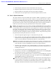
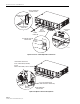
7.
Remove
the
dust
caps
from
the
optical
fiber
connectors
and
the
port
1
optical
transceiver.
Note:
Leave
the
dust
cap
in
place
on
any
unused
optical
transceiver.
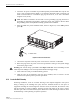
8.
Clean
each
connector
(follow
connector
supplier’s
recommendations)
and
then
insert
the
optical
fiber
connector
pair
into
DHU
optical
port
1
(see
Figure
19).
9.
Place
the
optical
fibers
within
the
cable
guides
provided
on
the
cable
management
tray
(see
Figure
19)
and
then
dress
and
secure
the
fibers
at
the
DHU
per
standard
industry
practice.
10.
Connect
the
forward
and
reverse
path
optical
fibers
to
the
DEU
or
the
DRU
as
specified
in
the
instructions
provided
with
that
unit.
11.
Use
the
designation
card
provided
(see
Figure
19)
to
indicate
the
location
and
name
of
the
DRU
or
DEU
that
is
connected
to
each
optical
fiber
pair.
The
designation
card
holder
may
be
attached
to
any
convenient
flat
surface
such
as
the
DHU
cable
management
tray
12.
Repeat
steps
1–11
for
each
remaining
optical
port.
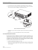
4.9 DC Power Connections
The
DC
power
interface
between
the
DHU
and
each
DRU
is
supported
by
six
RJ-45
female
connectors.
Each
DHU
RJ-45
connector
provides
nominal
48
Vdc
power
for
the
associated
DRU
except
when
the
DRU
is
powered
with
an
ac/dc
converter.
A
category
3
or
5
twisted
pair
cable
is
used
to
feed
the
power
from
the
DHU
to
the
DRU.
Use
the
following
procedure
to
install
the
DC
power
cable
and
to
connect
it
to
the
DHU.
1.
Obtain
the
required
length
of
category
3
or
5
twisted
pair
cable.
2.
Route
the
cable
between
the
DHU
and
the
DRU
(unless
already
routed)
and
then
cut
to
required
length.
Allow
sufficient
slack
for
dressing
and
organizing
the
cable
at
the
DHU.
Note:
The
maximum
distance
for
routing
power
cable
is
500
meters
(1,641
feet).
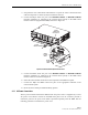
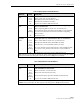
3.
Terminate
each
end
of
the
cable
with
a
male
RJ-45
connector.
Match
the
wire
color
to
the
connector
pin
as
specified
in
Table
6.
Caution:
The
DRU
will
be
damaged
if
the
RJ-45
connector
is
wired
incorrectly.
4.
Perform
a
continuity
test
to
verify
that
each
wire
is
properly
connected
to
the
terminating
RJ-45
connector
and
check
the
connector
for
correct
polarity
(see
diagram
in
Table
6).
Table 6. RJ-45 Connector Pin Designations
PIN NUMBER WIRE COLOR CONNECTOR PINS
1
2
3
4
5
6
7
8
White/Green
Green
White/Orange
Orange
White/Blue
Blue
White/Brown
Brown
PIN
1
PIN
8
+48 VDC ON PINS 1, 3, 5, AND 7
RETURN ON PINS 2, 4, 6, AND 8
16180-A